TDPACK (which stands for "Three Dimensional PACKage") is a collection of routines for projecting objects from a 3-dimensional coordinate system having U, V, and W axes to a 2-dimensional projection plane having X and Y axes and/or for drawing the projections of those objects. This can be referred to somewhat loosely as "drawing objects in three dimensions".
The following topics are addressed below:
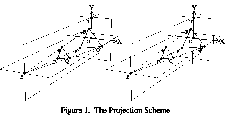
Consider Figure 1 (which is actually a crossed-eye stereo pair):

The user of TDPACK is expected to specify the positions of three points in the UVW system: 1) the point E where the eye is; 2) a point O toward which the eye is looking; and 3) a third point T, which may be thought of as "above" the point O. The line of sight is the line from E to O. The projection plane passes through O and is perpendicular to the line of sight. The plane passing through E, O, and T is the plane of bilateral symmetry of the viewer; its intersection with the projection plane is the Y axis. The X axis is perpendicular to the Y axis and passes through O, which is thus the origin of the XY coordinate system. All of these quantities are defined by calling the TDPACK routine TDINIT.
The basic object projected is a point in 3-space. The projection of such a point, P, is the point P' where the extension of the straight line from E to P intersects the projection plane. Figure 1 shows three such points - P, Q, and R - and their projections - P', Q', and R'. The principal point-projection routine in TDPACK is called TDPRPT.
The basic object drawn is the projection of the straight line segment joining two points in 3-space. Figure 1 shows three such line segments - PQ, QR, and RP - and their projections - P'Q', Q'R', and R'P'. The principal line-drawing routine in TDPACK is called TDLINE; an alternate version that calls DASHPACK routines and therefore allows one to draw a dashed line is called TDLNDP
A routine is also provided to draw the projection of a curve (as defined by N points in 3-space) and the curve may have a cone-shaped arrow on the end of it; the name of this routine is TDCURV. An alternate version that calls DASHPACK routines and therefore allows one to draw a dashed curve is called TDCUDP.
A perimeter, with or without tick marks or grid lines, can be drawn for each of the six faces of a box in 3-space. Numeric and informational labels can be drawn on selected edges of such a box. These more complicated objects are either formed from line segments or perhaps (in the case of character strings) from filled polygons. The TDPACK routines involved in this are TDPARA, which allows one to define a "reference parallelogram" within which a planar object is to be positioned; TDPRPA and TDPRPI, which map points from the reference parallelogram to the projection plane and vice-versa; TDLNPA, which draws lines in the reference parallelogram; TDLPDP, which draws lines in the reference parallelogram using calls to DASHPACK, so that the lines can be dashed; TDGRDS and TDGRID, which draw grids; TDLBLS and TDLBLA, which draw labels; and TDPLCH, which just draws character strings.
TDPACK is also capable of rendering simple surfaces, isosurfaces, markers, and sets of markers along a trajectory. The routines involved in this are TDSTRI, which generates triangles representing a simple surface, TDITRI, which generates triangles representing an isosurface, TDMTRI, which generates triangles representing a marker at a specified point, TDTTRI, which generates triangles representing a set of markers evenly spaced along a trajectory defined by a set of points, TDOTRI, which orders a collection of triangles for correct rendering, and TDDTRI. which draws a collection of triangles.
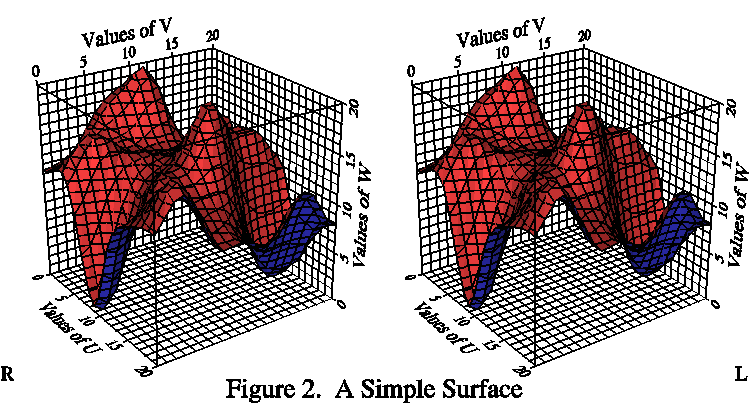
Figure 2 depicts a simple surface, as defined by a function w(u,v):

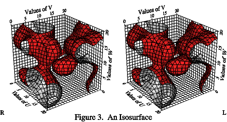
Figure 3 depicts an isosurface, as defined by an equation f(u,v,w)=C:

A surface is drawn by generating a collection of 3-space triangles whose union represents the surface and then rendering the projections of those triangles using the so-called "painter's algorithm": the triangles are processed in order of decreasing distance from the eye, so that projections of nearer ones are drawn on top of projections of further ones. Each triangle is generally first filled with a user-selected color (if a wire-frame image is desired, this step may be skipped); the fill color can be a specific one chosen by the user or one selected from a range of user-specified colors according to the angle between the line of sight and the plane of the triangle (which results in a shading of the surface). After the triangle is filled, line segments representing its boundary and/or its intersection with planes of constant U, V, and/or W may be drawn in a contrasting color.
The two sides of a given surface (the "top" and "bottom" of a simple surface, the "higher" and "lower" sides of an isosurface, or the "outside" and "inside" surfaces of a marker) can be shown differently (by making the depiction of each triangle depend on which side of it is visible).
A marker produced by calling TDMTRI or TDTTRI can be a tetrahedron, an octahedron, a cube, an icosahedron, or an elaborated icosahedron (effectively, a sphere). For examples of this, see Example 7 and C Example 1.
A possibility for the future is a routine making it possible to render images of the Earth (as represented by the EZMAP or World Data Bank II datasets) in a similar manner.
Note that the painter's algorithm for rendering surfaces is quite simple and straightforward to implement, but can lead to rather large metafiles, so it is not recommended to generate large numbers of images in batch mode.
Stereo views can easily be done using TDPACK: one just executes all of the object-drawing calls twice, the first time preceded by an initialization call for the left eye and the second time by an initialization call for the right eye. The final argument of TDINIT makes this easy to do.
To see the stereo effect, one must present the stereo pair in such a way that each eye sees the image intended for it. The simplest scheme (but the hardest for most people to use) is to just put the two images side by side. If the left eye's image is to the left and the right eye's image is to the right, the eyes must be aimed at a point beyond the projection plane; because the two images cannot be allowed to overlap and because few people can actually make their eyes diverge very much, the distance between like features of the two views must be less than the distance between the eyes of the viewer (about 2.5 inches) and the size of the resulting image is thus rather limited. If, on the other hand, the left eye's image is put on the right and the right eye's image is put on the left, then the eyes must be aimed at a point between the viewer and the projection plane (i.e., more or less crossed); this is a learned talent and seems to be difficult for most people to do without strain, but the images can then be larger. Figures 1, 2, and 3 are all of this type.
Old-fashioned stereoscopes used non-overlapping images and a set of lenses and/or prisms, allowing the eyes of the user to relax and focus "at infinity" while still allowing the use of quite large images.
One can draw large overlapping images in complementary colors and view them through glasses with a different filter for each eye, each of which transmits only one of the colors in the drawing, but this scheme is quite clumsy and has the disadvantage of not allowing for the full use of color in the images.
Modern stereo devices allow two large images to overlie one another, but still allow only one of the two to be seen by each eye. A typical device uses a stereo monitor that projects the two images in rapidly alternating time slices. The viewer wears glasses that are synchronized with the screen so as to present an image to only one eye at a time and to present each eye with only the images meant for it. This is very easy to use, causes no eyestrain, and gives excellent stereo views.
TDPACK has many "internal parameters" - variables in TDPACK common blocks - each of which affects some aspect of the behavior of the package. A typical internal parameter has a three-character mnemonic name and a default integer or real value that results in useful behavior; the value of the parameter can be retrieved by calling either TDGETI or TDGETR and changed by calling either TDSETI or TDSETR. There are some internal parameter arrays that define rendering styles; these are accessed by calling one of the routines TDGTRS (to retrieve a definition) or TDSTRS (to change the definition).
A complete list of the internal parameters may be found here.
The positions of some objects (for example, character strings and perimeters) are specified relative to a "reference parallelogram" in 3-space. At any given time, such a parallelogram is defined by internal parameters of TDPACK; there is a routine (TDPARA) whose only function is to allow redefinition of those internal parameters. For example, when one is drawing a grid on a particular face of the object box, one first defines the reference parallelogram to lie in one corner of that face and then draws the grid using calls defining points with reference to that parallelogram.