
The package EZMAP has acquired its current form over a number of years; several times, groups of routines implementing a particular new function have been added and each of these has a sort of subpackage name, as follows:
The following transformation routines were added to EZMAP in April, 2008, to make it possible to have two transformations defined and usable at the same time:
In mid-1999, an updated version of this database, called "Earth..2", was created; it contains everything "Earth..1" does, plus the provinces of Canada, the states of Mexico, the counties of the United States, the country called Eritrea, and the countries resulting from the breakup of the USSR that were not included in "Earth..1".
In the summer of 2000, a version of "Earth..2" was created which is just like it, but contains climate divisions of the US states instead of counties; it is called "Earth..3".
In 2008, a new database, called "Earth..4", was introduced. It is much like "Earth..2", but has about 10 times as much detail and is much more accurate. Its coastlines are simplified versions of those in the RANGS database and its political outlines match what one finds on a web site such as Wikimapia. It has state/province outlines for Australia, Brazil, China, and India. The ice shelves of Antarctica are included and, with the proper programming, can be made to appear or not, as desired.
Each area defined by the database has 1) an "area identifier" (an integer uniquely identifying it), 2) an "area type" specifying its level in a hierarchy of areas, 3) a suggested color index, 4) an area identifier specifying its "parent" area (the area of which it is a part), and 5) a name. For example, there is an area named "Madeline Island" which is of type 4 (used for a state or a portion thereof) and has suggested color index 6. Its parent is an area named "Wisconsin", which is also of type 4 and has suggested color index 6. The parent of "Wisconsin" is "Conterminous US", which is of type 3 (used for a country or a portion thereof) and has suggested color index 3. The parent of "Conterminous US" is "United States", which is also of type 3 and has suggested color index 3. The parent of "United States" is "North America", which is of type 2 and has suggested color index 5. The parent of "North America" is "Land", which is of type 1 and has suggested color index 2. The area named "Land" is at the top of the hierarchy and therefore has no parent (when you ask for the area identifier of its parent, you get a zero).
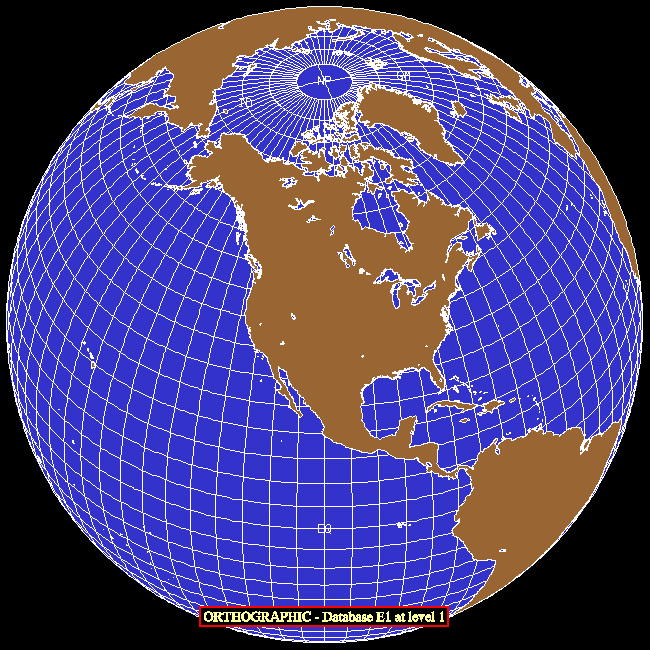
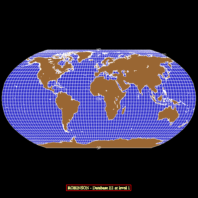
One may use the database at any of five specified hierarchical levels: 1 => land/water, 2 => continents, 3 => countries, 4 => states, and 5 => counties. When the database is used at a particular level, entities that exist only at lower levels (larger level numbers) effectively disappear.
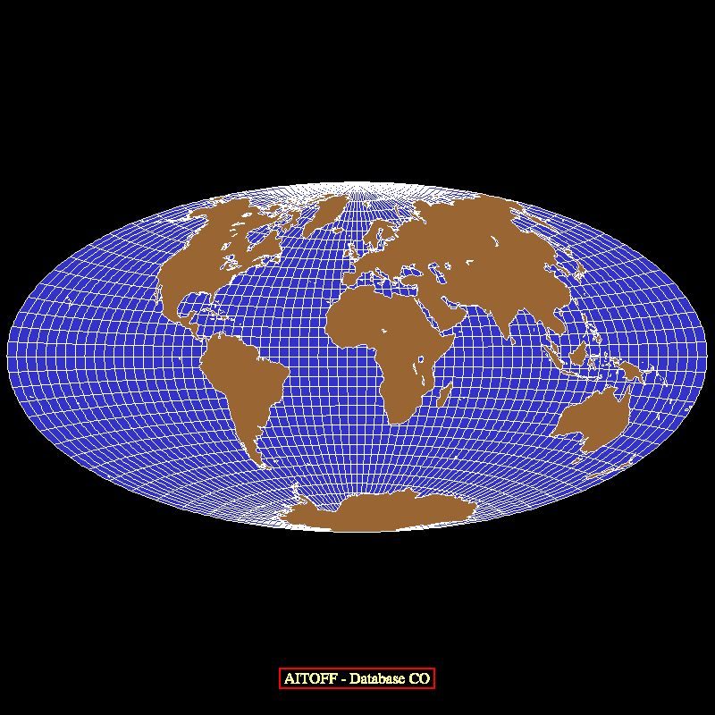
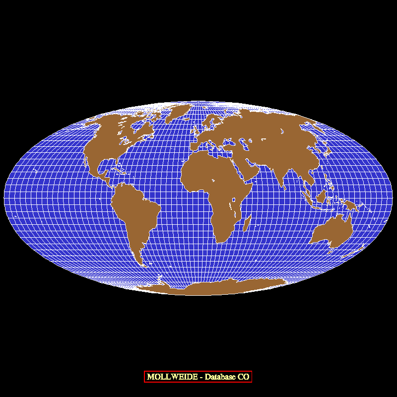
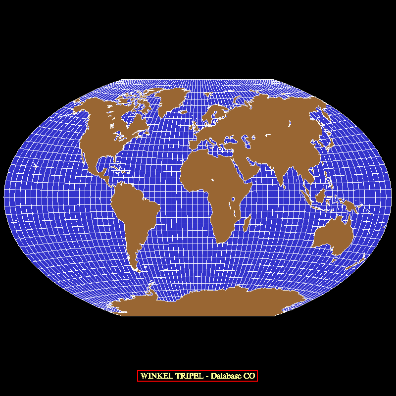
The new database was created from data available on the World Wide Web, using a new interactive editor based on NCAR Graphics. There are plans to make this editor available, so that a knowledgeable user can create a database tailored to his or her own needs: for example (assuming that one can obtain the necessary outline data), it should now be relatively easy to create and use a Pangaea database with EZMAP.
A new package of routines is used to access "Earth..1" and other databases in the same format; this package is called EZMAPB. Conceptually, the EZMAPB routines are just part of EZMAP; they use the same common blocks and many of the same underlying low-level routines and they are affected by the same set of internal parameters as the routines in EZMAP proper.
The principal EZMAPB routines are as follows:
The GCTP was intended to be run using 64-bit arithmetic on machines having 32-bit reals and therefore used double precision everywhere. On machines having 64-bit reals, this is unnecessary and may be very time-consuming; real arithmetic should be used instead. Therefore, each of the original GCTP routines exists in two different versions in our package - in single precision and in double precision. An EZMAP routine that needs to call a GCTP routine on a particular system calls whichever version of it is appropriate for use on that system.
On a machine having 32-bit reals, 64-bit double precision arithmetic is used in all computations within the GCTP, but the output values are truncated to 32 bits for plotting purposes; in this case, it is possible for a user with special needs to retrieve the 64-bit values directly.
The following user-level routines were added to EZMAP:
The "Global Self-consistent Hierarchical High-resolution Shoreline" (GSHHS) dataset was originally created by Paul Wessel, of SOEST (School of Ocean and Earth Science and Technology), at the University of Hawaii, Honolulu, Hawaii, and Walter H. F. Smith, of the NOAA Geosciences Lab, National Ocean Service, Silver Spring, Maryland, for use with the package "Generic Mapping Tools" (GMT). The data they used came from the public-domain datasets "World Databank II" (WDBII) and "World Vector Shoreline" (WVS), but they cleaned up the data greatly. The on-line documentation for GMT contains a description of the whole process. The GSHHS dataset may be used at any one of five different levels of resolution, characterized by the keywords "finest", "fine", "medium", "coarse" and "coarsest".
Subsequently, Riener Feistel, at the Baltic Sea Research Institute, in Warnemuende, Germany, added structure to the data, making it easier to use in limited regions, to create what he calls the "Regionally Accessible Nested Global Shorelines" (RANGS) dataset. For a complete description, look here.
The RANGS/GSHHS data may be downloaded from the NCAR Graphics site or from Feistel's site, above. The following files are required:
    rangs(0).cat:      259,200 bytes  }
    rangs(1).cat:      259,200 bytes  }
    rangs(2).cat:      259,200 bytes  }  RANGS "catalog" files.
    rangs(3).cat:      259,200 bytes  }
    rangs(4).cat:      259,200 bytes  }

    rangs(0).cel:    6,518,664 bytes  }
    rangs(1).cel:    5,945,492 bytes  }
    rangs(2).cel:    4,062,215 bytes  }  RANGS "cell" files.
    rangs(3).cel:    3,398,642 bytes  }
    rangs(4).cel:    3,045,848 bytes  }

    gshhs(0).rim:   89,496,428 bytes  }
    gshhs(1).rim:   20,775,224 bytes  }
    gshhs(2).rim:    5,099,196 bytes  }  GSHHS "rim" files.
    gshhs(3).rim:    1,109,192 bytes  }
    gshhs(4).rim:      170,948 bytes  }

    total length:  140,917,849 bytes
Files containing a "(0)" define the finest-resolution dataset, those
containing a "(1)" the next finest, and so on.The following user-level routines were added to EZMAP:
This change involved the addition of many new EZMAP entry points. With four exceptions (MAPGTD, MAPSTD, MPGETD, and MPSETD) that were created solely for the sake of consistency, the names of all the new entry points begin with the two characters "MD" (for "Maps, Double"). In general, the routines with new names, beginning with "MD", are now the principal ones, while the routines with older names, beginning with "MAP" or "MP", are implemented by calling the new ones; thus, there is a small advantage in using the new entry-point names, but all of the older ones will work. (Note, however, that the double-precision routines MDPGCI, MDGCOG, and MDRITD are not used by their single-precision analogues MAPGCI, NGGCOG, and NGRITD.)
The new entry points are detailed below:
First, since all internal parameters of type REAL were changed to be of type DOUBLE PRECISION, it was necessary to create six entirely new routines to set and retrieve parameter values:
      MDGETD = MPGETD = MAPGTD (DP parameter value retrieval)
      MDSETD = MPSETD = MAPSTD (DP parameter value setting)
Three new routines are just like existing routines that set internal
parameter values, but allow users to provide double-precision values:
      MDPPOS (like MAPPOS, sets map position parameters, has DP arguments)
      MDPROJ (like MAPROJ, sets projection parameters, has DP arguments)
      MDPSET (like MAPSET, sets map limit parameters, has DP arguments)
Three new routines allow access to double-precision versions of the
basic transformation routines (lat/lon to U/V and vice-versa):
      MDPTRA (like MAPTRA, transformation routine, has DP arguments)
      MDPTRI (like MAPTRI, transformation routine, has DP arguments)
      MDPTRN (like MAPTRN, transformation routine, has DP arguments)
Thirteen new routines are used for drawing objects using lat/lon
coordinates specified in double precision:
      In EZMAP,

      MDPGCI (like MAPGCI, interpolate points on great circle, has DP arguments)
      MDGCOG (like NGGCOG, create a great circle on globe, has DP arguments)
      MDRITD (like NGRITD, do 3D rotations, has DP arguments)

      MDPFST (like MAPFST, start a line, has DP lat/lon arguments)
      MDPVEC (like MAPVEC, continue a line, has DP lat/lon arguments)

      MDPIT  (like MAPIT, start or continue a line, has DP lat/lon arguments)
      MDPIQ  (like MAPIQ, finish drawing a line)
      MDPITD (like MAPITD, start or continue a line, has DP lat/lon arguments, using DASHPACK)
      MDPIQD (like MAPIQD, finish drawing a line, using DASHPACK)

      In EZMAPA,

      MDPITA (like MAPITA, line segment to area map, DP lat/lon arguments)
      MDPIQA (like MAPIQA, finish adding lines to an area map)
      MDPITM (like MAPITM,  draw line segment masked, DP lat/lon arguments)
      MDPIQM (like MAPIQM, finish drawing lines masked by an area map)
Four new routines are used to place latitude and longitude labels along a
specified line on the map (which becomes more important as one uses more
detailed large-scale maps):
      MDLBLN (puts longitude labels along a specified line on the map)
      MDLBLT (puts latitude labels along a specified line on the map)
      MDLACH (converts a double-precision latitude to character form)
      MDLOCH (converts a double-precision longitude to character form)
As of 01/24/2007, another four have been added, which are just like the
four immediately above, but express the labels in decimal degrees, rather
than in standard nautical form:
      MDLLND (puts longitude labels along a specified line on the map)
      MDLLTD (puts latitude labels along a specified line on the map)
      MDLACD (converts a double-precision latitude to character form)
      MDLOCD (converts a double-precision longitude to character form)
All the rest of the entry points were created solely for the sake of
consistency, so that new programs can be written using nothing but names
that begin with the characters "MD". These entry points are essentially
just alternate names for existing entry points and are used with the same
arguments as the originals:
      In EZMAP,

      MDGETC (like MPGETC = MAPGTC, parameter retrieval)
      MDGETI (like MPGETI = MAPGTI, parameter retrieval)
      MDGETL (like MPGETL = MAPGTL, parameter retrieval)
      MDGETR (like MPGETR = MAPGTR, parameter retrieval)
      MDPDRW (like MAPDRW, draw a complete map)
      MDPEOD (like MAPEOD, user-supplied routine to examine outline dataset)
      MDPGRD (like MAPGRD, draw a lat/lon grid)
      MDPINT (like MAPINT, initialize the package)
      MDPLBL (like MAPLBL, label a map)
      MDPLMB (like MAPLMB, draw a limb line)
      MDPLOT (like MAPLOT, draw geographic outlines)
      MDPRS  (like MAPRS, re-call SET)
      MDPRST (like MAPRST, restore saved parameter values)
      MDPSAV (like MAPSAV, save current parameter values)
      MDRSET (like MPRSET, parameter resetting)
      MDSETC (like MPSETC = MAPSTC, parameter setting)
      MDSETI (like MPSETI = MAPSTI, parameter setting)
      MDSETL (like MPSETL = MAPSTL, parameter setting)
      MDSETR (like MPSETR = MAPSTR, parameter setting)
      MDPUSR (like MAPUSR, user-supplied routine to change line style, color, etc.)

      In EZMAPA,

      MDPACI (like MAPACI, get suggested color index for specified area)
      MDPBLA (like MAPBLA, put boundary lines in an area map)
      MDPBLM (like MAPBLM, draw boundary lines masked by an area map)
      MDPGRM (like MAPGRM, draw a lat/lon grid masked by an area map)
      MDPLMM (like MAPLMB, draw a limb line masked by an area map)

      In EZMAPB,

      MDCHLN (like MPCHLN, change settings affecting lines being drawn)
      MDFNME (like MPFNME, get full name of an area)
      MDGLTY (like MPGLTY, get line type of current line being drawn)
      MDIATY (like MPIATY, get area type of an area)
      MDIFNB (like MPIFNB, get index of first non-blank of a string)
      MDILNB (like MPILNB, get index of last non-blank of a string)
      MDIOLA (like MPIOLA, get id of largest area containing an area)
      MDIOSA (like MPIOSA, get id of smallest area containing an area)
      MDIPAI (like MPIPAI, check whether an area is part of another)
      MDIPAN (like MPIPAN, check whether an area is part of another)
      MDIPAR (like MPIPAR, get id of parent area of an area)
      MDISCI (like MPISCI, get suggested color index for an area)
      MDLNAM (like MPLNAM, put outlines in an area map)
      MDLNDM (like MPLNDM, draw outlines masked by an area map)
      MDLNDR (like MPLNDR, draw outlines)
      MDLNRI (like MPLNRI, read information from an outline dataset)
      MDNAME (like MPNAME, get the name of an area)

      In EZMAPC,

      MDUTIN (like MPUTIN, USGS transform initialization)

      MDUTFD (like MPUTFD, USGS transform, forward, double precision)
      MDUTFS (like MPUTFS, USGS transform, forward, single precision)
      MDUTID (like MPUTID, USGS transform, inverse, double precision)
      MDUTIS (like MPUTIS, USGS transform, inverse, single precision)
The cone intersects the earth along two user-specified standard parallels (lines of latitude), which would normally both be in the Northern Hemisphere or in the Southern Hemisphere; the cone is cut along the line opposite a user-specified central meridian (line of longitude) and laid flat on the u/v plane with either the North Pole or the South Pole (as implied by the standard parallels) at the origin.
If LAT1 and LAT2 are the latitudes of the two standard parallels and LAT1 is not equal to LAT2, the so-called "cone constant" is given by the formula
                 LOG(COS(LAT1))-LOG(COS(LAT2))
    CONE = -------------------------------------------
           LOG(TAN(45-S*LAT1/2))-LOG(TAN(45-S*LAT2/2))
where "S" is +1 in the Northern Hemisphere and -1 in the Southern
Hemisphere. If LAT1 equals LAT2, then
CONE = COS(90-S*LAT1)
The value of CONE is between 0 and 1; CONE*360 is the angular separation
between the edges of the cut after the cone is opened onto the plane, as
measured across the surface of the flattened cone. If (RLAT,RLON) is a
point to be projected, then the formulas
    R = (TAN(45-S*RLAT/2))**CONE
    U = R*SIN(CONE*(RLON-CLON))
    V = -S*R*COS(CONE*(RLON-CLON))
where CLON is the longitude of the central meridian, give the coordinates
of the projected point in the u/v plane.The globe is projected onto the entire u/v plane minus a wedge with its apex at the origin. This projection is normally used to depict mid-latitude regions of limited extent, for which it is relatively distortion-free. It has the property of preserving angles.
See the example named "mpex01".
R = TAN(A/2) = (1-COSA)/SINA
R = SINA
R = 2*SINA/SQRT(2*(1+COSA))
R = TAN(A) = SINA/COSA
R = A*pi/180
R = SQRT(SA*SA-1)*SINA/(SA-COSA)
R = (something messy that I don't have in closed form)!
      U = RLON
      V = RLAT
      U = RLON
      V = RLAT/COS(SLAT)

      SLAT is a standard parallel - by default, SLAT = ACOS(2/pi)
      U = RLON*pi/180 (where pi=3.14159...)
      V = SIN(RLAT)/COS(SLAT)**2

      SLAT is a standard parallel - by default, SLAT = pi/6 = 30 degrees
      U = RLON*pi/180 (where pi=3.14159...)
      V = ALOG(COT(45-RLAT/2))
      U = (RLON/90)*COS(RLAT)
      V = SIN(RLAT)
      RLAT     PLEN      PDFE
      ----    ------    ------
       00N    1.0000    0.0000
       05N    0.9986    0.0620
       10N    0.9954    0.1240
       15N    0.9900    0.1860
       20N    0.9822    0.2480
       25N    0.9730    0.3100
       30N    0.9600    0.3720
       35N    0.9427    0.4340
       40N    0.9216    0.4958
       45N    0.8962    0.5571
       50N    0.8679    0.6176
       55N    0.8350    0.6769
       60N    0.7986    0.7346
       65N    0.7597    0.7903
       70N    0.7186    0.8435
       75N    0.6732    0.8936
       80N    0.6213    0.9394
       85N    0.5722    0.9761
       90N    0.5322    1.0000
      U = 2*COS(RLAT)*SIN(RLON/2)/SINC(ALPH)
      V = SIN(RLAT)/SINC(ALPH)

      where

      ALPH = ACOS(COS(RLAT)*COS(RLON/2))

      and

      SINC(ALPH) = SIN(ALPH)/ALPH for ALPH non-zero; 1 for ALPH equal to zero
      U = 2*SQRT(2)*COS(RLAT)*SIN(RLON/2)/SQRT(1+COS(RLAT)*COS(RLON/2))
      V = SQRT(2)*SIN(RLAT)/SQRT(1+COS(RLAT)*COS(RLON/2))
      U = 2*SQRT(2)*(RLON/180)*COS(THTA)
      V = SQRT(2)*SIN(THTA)

      where

      2*THTA+SIN(2*THTA) = pi*SIN(RLAT)

      (THTA is computed using a Newton-Raphson iteration.)
      U = (RLON*COS(SLAT)+2*COS(RLAT)*SIN(RLON/2)/SINC(ALPH))/2
      V = (RLAT+SIN(RLAT)/SINC(ALPH))/2

      where

      ALPH = ACOS(COS(RLAT)*COS(RLON/2))

      and

      SINC(ALPH) = SIN(ALPH)/ALPH for ALPH non-zero; 1 for ALPH equal to zero

      and

      SLAT is a standard parallel - by default, SLAT = ACOS(2/pi)
In order to use the USGS routines, one must first call the routine MDPROJ with a first argument 'UT' (for "USGS Transformations"). Then, one must call the routine MDUTIN to select a particular USGS transformation and initialize it. MDUTIN calls MDPINT, and subsequent calls are just as before.
Some of the USGS transformations are for projections that we did not previously have. Some of them are for projections that we did have, but provide for the use of an ellipsoidal model of the earth instead of or in addition to a spherical model. In all cases, one can specify the dimensions of the earth in meters, so that U and V coordinates have real meaning.
The projections provided by the USGS are as follows:
| No. | Name | Type | Earth Model | Shape of Projected Earth |
|---|---|---|---|---|
| 01 | UTM (Universal Transverse Mercator) | cylindrical | ellipsoid | not used for whole-earth maps |
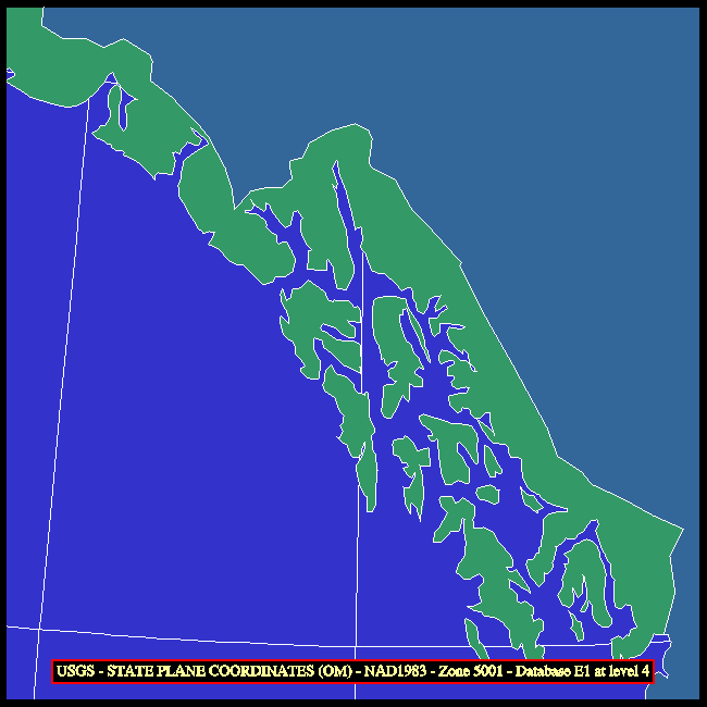
| 02 | State Plane | various | ellipsoid (Clarke 1866 or GRS 1980 only) | not used for whole-earth maps |
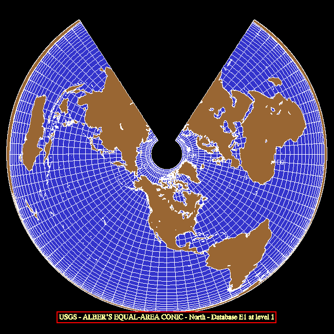
| 03 | Albers Equal-Area Conic | conical | ellipsoid | interior of a circle minus a smaller circle and a wedge |
| 04 | Lambert Conformal Conic | conical | ellipsoid | entire plane minus a wedge |
| 05 | Mercator | cylindrical | ellipsoid | strip between vertical lines |
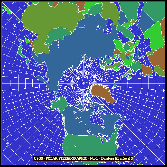
| 06 | Polar Stereographic | azimuthal | ellipsoid | entire plane |
| 07 | Polyconic | conical | ellipsoid | interior of a near-circle |
| 08 | Equidistant Conic | conical | ellipsoid | interior of a circle minus a smaller circle and a wedge |
| 09 | Transverse Mercator | cylindrical | ellipsoid | strip between horizontal lines |
| 10 | Stereographic | azimuthal | sphere of reference | entire plane |
| 11 | Lambert Azimuthal Equal-Area | azimuthal | sphere of reference | interior of a circle |
| 12 | Azimuthal Equidistant | azimuthal | sphere of reference | interior of a circle |
| 13 | Gnomonic | azimuthal | sphere of reference | entire plane |
| 14 | Orthographic | azimuthal | sphere of reference | interior of a circle |
| 15 | Perspective | azimuthal | sphere of reference | interior of a circle |
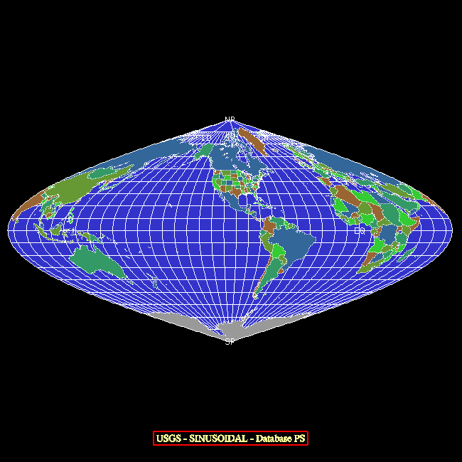
| 16 | Sinusoidal | cylindrical | sphere of reference | area between two sine curves |
| 17 | Equirectangular | cylindrical | sphere of reference | interior of a rectangle |
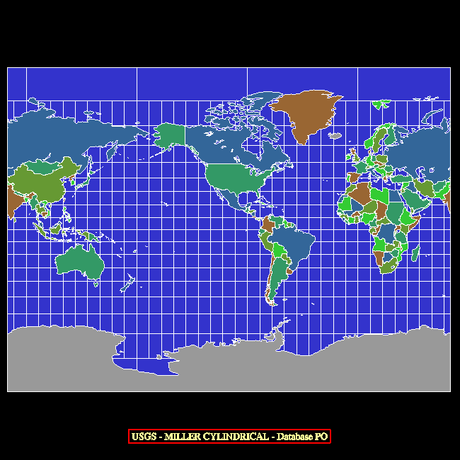
| 18 | Miller Cylindrical | cylindrical | sphere of reference | interior of a rectangle |
| 19 | Van der Grinten I | cylindrical | sphere of reference | interior of a circle |
| 20 | Oblique Mercator (Hotine) | cylindrical | ellipsoid | strip between oblique lines |
| 21 | Robinson | pseudocylindrical | sphere of reference | interior of a polygon |
| 22 | Space Oblique Mercator | cylindrical | ellipsoid | really, really weird - useful in limited areas |
| 23 | Modified Stereographic for Alaska | azimuthal | ellipsoid (Clarke 1866 only) | not used for whole-earth maps |
The UTM system takes advantage of the fact that a transverse Mercator projection of the earth is generated using a cylinder whose axis is perpendicular to the plane of a particular meridian and portrays with minimal distortion a strip of the earth's surface near that meridian, where the surface of the earth and the cylinder are very close together.
The portion of the earth between latitudes 80S and 84N is divided into 60 longitude zones, each of which is 6 degrees of longitude in width. The zones are numbered consecutively from west to east; zone number 1 is centered at 177W and covers longitudes from 180W to 174W and zone number 60 is centered at 177E and covers longitudes from 174E to 180E. Each of the sixty UTM zones is projected to an X/Y plane using a transverse Mercator projection having the central meridian of the zone as its central meridian. Given the latitude and longitude of a point in a UTM zone, the transverse Mercator projection gives us an X value, referred to as an "easting", and a Y value, referred to as a "northing", for the point; these are the numeric UTM coordinates of the point and they are measured in meters. Eastings are biased by the addition of a "false easting", so that a point on the central meridian always has an easting of exactly 500,000. The northing for a point in the Northern Hemisphere is just its distance from the equator, but the northing for a point in the Southern Hemisphere is biased by a "false northing" of 10,000,000 (so that subtracting it from 10,000,000 gives the distance of the point from the equator). The use of the "false easting" and "false northing" ensures that the UTM coordinates will always be positive values.
Thus, given a point at an arbitrary longitude and a latitude between 80S and 84N, one can determine the zone and the hemisphere in which the point lies and then compute its numeric UTM coordinates relative to that zone. Similarly, given a zone number, a hemisphere, and the numeric UTM coordinates of a point, one can determine the latitude and longitude of the point.
Each of the sixty UTM zones is further subdivided into twenty horizontal bands, which are lettered, from south to north, beginning with "C" for a band from 80S to 72S and ending with "X" for a band from 72N to 84N; the letters I and O are skipped to avoid confusion with the numbers 1 and 0. Each of the first nineteen bands spans eight degrees of latitude, while the northernmost band, band "X", spans 12 degrees of latitude.
Note that the information provided by the horizontal-band letters is somewhat redundant: although specifying the letter gives someone who is familiar with the UTM system a rough idea of where on the earth a point lies, it affects the computation of the lat/lon coordinates from the numeric UTM coordinates only in that one can deduce from the letter whether a specified point is in the Southern Hemisphere (bands C-M) or in the Northern Hemisphere (bands N-X).
The USGS routines do not make use of the band letters in UTM coordinates; instead, the convention is that positive zone numbers, from 1 to 60, refer to the Northern Hemisphere and negative zone numbers, from -1 to -60, refer to the Southern Hemisphere. As far as I know, this convention is peculiar to the USGS routines and is not used elsewhere.
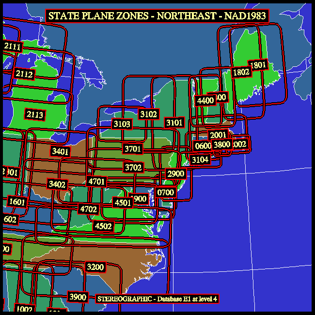
There are two different versions of the State Plane system, an older one based on the "North American datum of 1927 (NAD27)", which uses the "Clarke 1866" spheroid, and a newer one based on the "North American datum of 1983 (NAD83)", which uses the "GRS 1980" spheroid. In either version, a four-digit "zone number" specifies the area of interest; for example, zone number "2800" refers to New Hampshire. The sets of zone numbers used in the two versions are similar, but not identical: for example, in both versions, Delaware is zone number "0700", but the older version of Montana is divided into zones "2501", "2502", and "2503" ("North", "Central", and "South"), while the newer version of Montana is just zone number "2500".
The principal projections used by the State Plane system are the Lambert Conformal Conic with two standard parallels and the Transverse Mercator secant to the model of the earth; there is also a single zone for which the Polyconic is used and another for which the Oblique Mercator is used. Distortion in the Lambert Conformal Conic is a function of latitude, but is independent of longitude, so it is used for areas having a greater extent in longitude than in latitude; the scale is true along each of the standard parallels. Similarly, distortion in the Transverse Mercator is a function of longitude, but is independent of latitude, so it is used for areas having a greater extent in latitude than in longitude; the scale is true along each of two lines roughly parallel to the central meridian.
For each of the State Plane coordinate zones, projection parameters are defined so that the point having a given latitude and longitude has coordinates X and Y (referred to as the "easting" and "northing", respectively) in the projection space; X and Y are measured in meters. The coordinates are offset by addition of a "false easting" and a "false northing" which are defined in such a way as to make the coordinates of all points within the area of interest be positive.
When one calls MDUTIN to initialize the USGS package for a particular State Plane zone without specifying the ranges of X and Y coordinates to be displayed, the routine sets those ranges in such a way as to show the approximate intended extent of that zone. The EZMAP demo program can be made to draw plots of the State Plane zones in a specified area.
Draws a complete map, as described by the current values of the internal parameters of EZMAP. Note that this routine uses whichever old outline dataset is selected by the value of the internal parameter 'OU'; to access the new map databases "Earth..1", "Earth..2", "Earth..3", and "Earth..4", one must call instead the routines that MDPDRW would have called, but call MDLNDR (which see) instead of MDPLOT.
Users may sometimes wish to call directly the routines that MDPDRW calls. For example, they sometimes want to change the aspect ratio of a map drawn by EZMAP to something other than that implied by the projection selected; in order to do this, it is necessary to put calls to GETSET and SET in between the call to MDPINT and the calls to MDPGRD, MDPLBL, and MDPLOT. This is possible only if the user is calling those routines directly (rather than indirectly, by calling MDPDRW).
See the examples named "mpex01", "mpex02", "mpex04", "mpex05", "mpex06", "mpex07", and "mpex10".
An initialization routine. As of early 1999, EZMAP keeps track of its own initialization state and does its own calls to the routine MDPINT. Therefore, it is no longer necessary for a user to call it; however, such a call will do no harm.
The routines MAQINI and MDQINI are much like MAPINT and MDPINT, respectively; they were added in April, 2008, and may be called at any time to save the current transformation for use by subsequent calls to MAQTRA, MAQTRI, MAQTRN, MDQTRA, MDQTRI, and MDQTRN, thus making it possible to have two different transformations defined at the same time. These routines were implemented in support of the ability to use a PNG as a background for an EZMAP plot.
CALL MDPINT
initializes the EZMAP package. This is required initially and again
after a call to any of the routines MDPPOS, MDPROJ, or MDPSET. The
flag 'IN', which may be retrieved by a call to MDGETI or MDGETL,
indicates whether or not initialization is required at a given time.
As of now (April, 1987), no parameter change by means of a call to
MDSETx forces re-initialization; only calls to MDPPOS, MDPROJ, and
MDPSET do.To clarify the use of MDPINT: Once the internal parameters describing a map transformation are completely defined, MDPINT must be called; it computes as many of the transformation parameters as possible, so that, when MDPTRN is called, it can return the u/v coordinates corresponding to a particular lat/lon position as quickly as possible. If the transformation is changed, MDPINT must be re-called before the next call to MDPTRN. Routines which call MDPTRN and therefore depend on MDPINT's having been called are as follows: MDPBLA, MDPFST, MDPGRD, MDPGRM, MDPIQ, MDPIQA, MDPIQM, MDPIT, MDPITA, MDPITM, MDPLBL, MDPLOT, MDPTRA, MDPTRI, MDPVEC, MDLNAM, MDLNDM, MDLNDR, MDRGOL, MDRGSF, and SUPCON. Routines which change the transformation in some way and therefore require MDPINT to be re-called are as follows: MDPPOS, MDPROJ, and MDPSET. If one is just doing a single plot, one does the parameter-setting calls that define the transformation, calls MDPINT to initialize, and then calls the various routines that draw the plot; in this case, a single call to MDPINT is all that is necessary.
One of the things that MDPINT does is call the SPPS routine SET to define the mapping from the u/v (projection) plane to the x/y (plotter) plane, so that u/v coordinates returned by the routines MDPTRA and MDPTRN can be used directly (as "user" coordinates) in calls to other NCAR Graphics routines. The user must be careful not to interfere with this process by doing an inappropriate call to SET in between calling MDPINT and calling other routines that depend on the proper SET call's having been done; if such a call must be done, the routine MDPRS (q.v.) may be used to restore the SET call done by MDPINT.
See the examples named "mpex09", "mpex10", and "eezmpa".
Draws a lat/lon grid.
CALL MDPGRD
draws a grid consisting of lines of latitude (parallels) and lines of
longitude (meridians).In addition to the grid, MDPGRD also draws the limb line (if any) of the current projection. For more information about limb lines, see the description of the routine MDPLMB.
If EZMAP needs initialization or if there is an uncleared NCAR Graphics error or if the parameter 'GR' is less than or equal to zero, MDPGRD does nothing.
The grid is drawn using calls to MDPIT and MDPIQ. By default, MDPGRD forces the value of the internal parameter 'DL' to zero, so that the grid will be drawn using calls to the routines FRSTD and VECTD, in the dash package. MDPGRD also calls the dash-package routine DASHDB to force the current dash pattern to the value specified by the internal parameter 'DA'. Before returning control to the user, MDPGRD restores the original value of 'DL' and the original dash pattern. A user version of one of the routines MAPUSR or MDPUSR may be supplied to change the way in which the grid lines are drawn (as shown in the example "mpex09").
The values of the parameters 'GP', 'GN', and 'GT' also affect the drawing of the grid.
Labels the map.
CALL MDPLBL
if the parameter 'LA' is set appropriately, labels the international
date line (ID), the equator (EQ), the Greenwich Meridian (GM), and the
poles (NP and SP), and, if the parameter 'PE' is set appropriately,
draws the perimeter of the map. If EZMAP needs initialization or if
there is an uncleared NCAR Graphics error, MDPLBL does nothing.See the example named "eezmpa".
Draws geographical outlines. Note that this routine uses whichever old outline dataset is selected by the value of the internal parameter 'OU'; to access the new map databases "Earth..1", "Earth..2", "Earth..3", and "Earth..4", one must call instead the EZMAPB routine MDLNDR.
CALL MDPLOT
draws the continental and/or international and/or U.S. state outlines
selected by the EZMAP parameter 'OU'; the parameter 'DO' determines
whether solid lines or dotted lines are used.If the internal parameter 'GR' has been given a negative value, MDPLOT will also draw the limb line (if any) of the current projection. For more information about limb lines, see the description of the routine MDPLMB.
If EZMAP currently needs initialization or if there is an uncleared NCAR Graphics error, MDPLOT does nothing.
The outlines are drawn using calls to MAPIT and MAPIQ, which call MDPIT and MDPIQ, respectively. By default, MDPLOT forces the value of the internal parameter 'DL' equal to the value of the internal parameter 'DO'; it also supplies the dash package with a solid-line dash pattern. When 'DO' is zero, the outlines are drawn using calls to the routines FRSTD and VECTD, in the dash package, and this gives solid lines. When 'DO' is non-zero, the outlines are drawn using calls to the SPPS routine POINTS, which gives dotted lines. Before returning control to the user, MDPLOT restores the original value of 'DL' and the original dash pattern. A user version of the routine MDPUSR may be supplied to change the way in which the outlines are drawn (as shown in the example "mpex09").
See the examples named "mpex09" and "eezmpa".
Positions the map on the plotter frame.
CALL MDPPOS (XLOW,XROW,YBOW,YTOW)
sets four EZMAP parameters specifying the position of a window in the
plotter frame within which maps are to be drawn. Each of the arguments
is between 0. and 1., inclusive, and specifies the position of one edge
of the window, as a fraction of the distance from left to right, or from
bottom to top, across the window. The map is centered within the window
and made as large as possible, but maintains its intrinsic shape (aspect
ratio).If it is desired to give a map a different aspect ratio than that implied by the projection being used, it will be necessary to insert, immediately after the call to MDPINT, an appropriate call to SET to override the one done by MDPINT and therefore to specify precisely the mapping of the u/v plane into a desired viewport on the plotter frame. Typically, one might call GETSET to find out what arguments 5-8 should be in one's own call to SET. Note that, if MDPDRW is being called, that call will have to be replaced by calls directly to MDPINT, MDPGRD, MDPLBL, and MDPLOT, in order to allow one's own call to SET to be placed immediately after the call to MDPINT.
See the examples named "mpex04", "mpex05", "mpex06", and "mpex07".
XROW (an input expression, of type REAL or DOUBLE PRECISON, depending on which routine is called) specifies the position of the right edge of the window. The default is .95.
YBOW (an input expression, of type REAL or DOUBLE PRECISON, depending on which routine is called) specifies the position of the bottom edge of the window. The default is .05.
YTOW (an input expression, of type REAL or DOUBLE PRECISON, depending on which routine is called) specifies the position of the top edge of the window. The default is .95.
Set the projection to be used.
CALL MDPROJ (JPRJ,PLAT,PLON,ROTA)
sets EZMAP parameters specifying the projection to be used for subsequent
maps.See the examples named "mpex01", "mpex02", "mpex04", "mpex05", "mpex06", "mpex07", "mpex09", "mpex10", and "eezmpa".
The conic projection:
PLAT, PLON, and ROTA (input expressions, of type REAL or DOUBLE PRECISION, depending on which routine is called) are angular quantities, in degrees. How they are used depends on the value of JPRJ, as follows:
To set internal parameters specifying the rectangular portion of the u/v plane to be drawn.
CALL MDPSET (JLTS,PLM1,PLM2,PLM3,PLM4)
specifies what portion of the u/v plane is to be drawn.See the examples named "mpex01", "mpex02", "mpex04", "mpex07", "mpex09", "mpex10", and "eezmpa".
To set the values of internal parameters of EZMAP.
      CALL MAPSTC (PNAM,CVAL) or CALL MPSETC (PNAM,CVAL) or CALL MDSETC (PNAM,CVAL)
      CALL MAPSTI (PNAM,IVAL) or CALL MPSETI (PNAM,IVAL) or CALL MDSETI (PNAM,IVAL)
      CALL MAPSTL (PNAM,LVAL) or CALL MPSETL (PNAM,LVAL) or CALL MDSETL (PNAM,LVAL)
      CALL MAPSTR (PNAM,RVAL) or CALL MPSETR (PNAM,RVAL) or CALL MDSETR (PNAM,RVAL)
      CALL MAPSTD (PNAM,DVAL) or CALL MPSETD (PNAM,DVAL) or CALL MDSETD (PNAM,DVAL)
depending on whether the value to be set is of type CHARACTER, INTEGER,
LOGICAL, REAL, or DOUBLE PRECISION. Some parameters may be set in more
than one way. For
example, the parameter 'GR', which specifies the grid spacing, may be
given the value 10.0 in either of three ways:
      CALL MDSETI ('GR',10)
      CALL MDSETR ('GR',10.)
      CALL MDSETD ('GR',10.D0)
The flag which controls dotting of outlines may be turned on using either
of these calls:
      CALL MDSETI ('DO',1)
      CALL MDSETL ('DO',.TRUE.)
The important point to remember is that the last character of the routine
name implies the type of its second argument.See the examples named "mpex01", "mpex02", "mpex04", "mpex05", "mpex06", "mpex07", "mpex08", "mpex09", "mpex10", "mpexfi", and "eezmpa".
xVAL (an input expression of type CHARACTER, INTEGER, LOGICAL, REAL, or DOUBLE PRECISION, depending on which routine is called) contains the value to be given to the parameter specified by PNAM.
See the section "INTERNAL PARAMETERS" for descriptions of all the internal parameters.
Gets the current value of a specified EZMAP parameter.
      CALL MAPGTC (PNAM,CVAL) or CALL MPGETC (PNAM,CVAL) or CALL MDGETC (PNAM,CVAL)
      CALL MAPGTI (PNAM,IVAL) or CALL MPGETI (PNAM,IVAL) or CALL MDGETI (PNAM,IVAL)
      CALL MAPGTL (PNAM,LVAL) or CALL MPGETL (PNAM,LVAL) or CALL MDGETL (PNAM,LVAL)
      CALL MAPGTR (PNAM,RVAL) or CALL MPGETR (PNAM,RVAL) or CALL MDGETR (PNAM,RVAL)
      CALL MAPGTD (PNAM,DVAL) or CALL MPGETD (PNAM,DVAL) or CALL MDGETD (PNAM,DVAL)
depending on whether the value to be retrieved is of type CHARACTER,
INTEGER, LOGICAL, REAL, or DOUBLE PRECISION. The values of some
parameters may be retrieved in more than one way. For example, the value
of the initialization flag
may be retrieved as a logical quantity (.TRUE. or .FALSE.) or as an
integer (non-zero or zero).See the examples named "mpex07" and "mpex08".
xVAL (an output variable of type CHARACTER, INTEGER, LOGICAL, REAL, or DOUBLE PRECISION, depending on which routine is called) receives the value of the parameter specified by PNAM.
Resets the internal state of EZMAP to the default.
CALL MDRSET
may be used to reset the values of all the internal parameters of
EZMAP to their defaults and then recall the initialization routine
MDPINT.
Saves the current state of EZMAP for later restoration by MDPRST.
CALL MDPSAV (IFNO)
saves the current state of EZMAP by
writing, on the unit specified by IFNO, the current values of all the
user-settable parameters.No example is available for MDPSAV.
Restores the state of EZMAP saved by an earlier call to MDPSAV.
CALL MDPRST (IFNO)
restores EZMAP to a previously saved state
by reading, from the unit specified by IFNO, values of all user-settable
parameters, and then executing MDPINT.No example is available for MDPRST.
The routines MAQTRN and MDQTRN were added in April, 2008, to support the use of alternate transformations. They are just like MAPTRN and MDPTRN, respectively, but use the transformation saved by the last call to MAQINI or MDQINI.
To project points.
CALL MDPTRN (RLAT,RLON,UVAL,VVAL)
may be used to find the projection in the u/v plane of a point whose
latitude and longitude are known. MDPTRN may be called at
any time after EZMAP has been initialized (by calling MDPINT or
otherwise).See the example named "mpex09".
UVAL and VVAL (output variables, of type REAL or DOUBLE PRECISION, depending on which routine is called) define the point (UVAL,VVAL) that is the projection in the u/v plane of (RLAT,RLON). The units of UVAL and VVAL depend on the projection.
If the point is not projectable, UVAL is returned equal to 1.E12 or 1.D12, depending on which routine is called. Note that, if the point is projectable, but outside the boundary of the map, as defined by the last call to MDPSET, its u and v coordinates are still returned by MDPTRN. The user must do the test required to determine if the point is within limits, if that is necessary.
To project points.
MDPTRA is just like MDPTRN except that, if a point being projected is outside the boundary of the map (as defined by the last call to MDPSET and by the value of the internal parameter 'EL'), a special value is returned to signal this condition; see the sub-section named "Arguments", below. (The default version of the CONPACK routine named CPMPXY now calls MAPTRA, rather than MAPTRN; it was for this purpose that MAPTRA and MDPTRA were created, but users may wish to call them, as well.)
The routines MAQTRA and MDQTRA were added in April, 2008, to support the use of alternate transformations. They are just like MAPTRA and MDPTRA, respectively, but use the transformation saved by the last call to MAQINI or MDQINI.
CALL MDPTRA (RLAT,RLON,UVAL,VVAL)
may be used to find the projection in the u/v plane of a point whose
latitude and longitude are known. MDPTRA may be called at
any time after EZMAP has been initialized (by calling MDPINT
or otherwise).Currently, no example is available for MDPTRA.
UVAL and VVAL (output variables, of type REAL or DOUBLE PRECISION, depending on which routine is called) define the point (UVAL,VVAL) that is the projection in the u/v plane of (RLAT,RLON). The units of UVAL and VVAL depend on the projection.
If the point is not projectable or if it is outside the boundary of the map, as defined by the last call to MDPSET and by the value of the parameter 'EL', UVAL is returned equal to 1.E12 or 1.D12, depending on which routine is called.
The routines MAQTRI and MDQTRI were added in April, 2008, to support the use of alternate transformations. They are just like MAPTRI and MDPTRI, respectively, but use the transformation saved by the last call to MAQINI or MDQINI.
To perform inverse transformations.
CALL MDPTRI (UVAL,VVAL,RLAT,RLON)
is used to find the latitude and longitude of a point whose projection
in the u/v plane is known. MDPTRI may be called at any time after EZMAP
has been initialized (by calling MDPINT or otherwise).
See the example named "mpex10".
RLAT and RLON (output variables, of type REAL or DOUBLE PRECISION ) are the latitude and longitude, respectively, of the point, in degrees. RLAT will be between -90. and +90., inclusive; RLON will be between -180. and +180., inclusive.
If the point (UVAL,VVAL) is not the projection of some point of the globe or is outside the boundary of the map, RLAT and RLON are returned equal to 1.E12 or 1.D12, depending on which routine is called.
Draws lines on a map - used in conjunction with MDPVEC.
CALL MDPFST (RLAT,RLON)
is equivalent to the statement
CALL MDPIT (RLAT,RLON,0)
See the description of MDPIT.
Draws lines on a map - used in conjunction with MDPFST.
CALL MDPVEC (RLAT,RLON)
is equivalent to the statement
CALL MDPIT (RLAT,RLON,1)
See the description of MDPIT.
Draws lines on a map.
The EZMAP parameter 'DL' determines whether MDPIT draws solid lines or dotted lines. Dotted lines are drawn using calls to POINTS. Solid lines are drawn using calls to DASHD, FRSTD, and VECTD. The EZMAP parameters 'DD' and 'MV' also affect MDPIT's behavior. See the description of these parameters in the section "INTERNAL PARAMETERS".
A sequence of calls to MDPIT should be followed by a call to MDPIQ to flush its buffers before a STOP, a CALL FRAME, or a call to change the color index, line width, dash pattern, or the like.
Beware of intermingling calls to MDPIT and calls to MDPITD; the two routines share buffer space and intermingling the calls will have undesirable effects.
Because the entire line segment joining the points in two contiguous pen-down calls to MDPIT is considered visible if both of the points are visible and invisible if both of the points are invisible, such points should not be too far apart on the globe.
See the example named "mpexfi".
IFST (an input expression, of type INTEGER) is 0 to do a "pen-up" move, 1 to do a "pen-down" move only if the distance from the last point to the new point is greater than 'MV' plotter units, and 2 or greater to do a "pen-down" move regardless of the distance from the last point to the new one.
Terminate a string of calls to MDPIT.
CALL MDPIQ
flushes MDPIT's buffers. It is particularly important that this be
done before a STOP or a CALL FRAME and before changing the color index,
dash pattern, etc.See the description of MDPIT.
See the example named "mpexfi".
Draws lines on a map using the new dash package DASHPACK.
The EZMAP parameter 'DL' determines whether MDPITD draws solid lines or dotted lines. Dotted lines are drawn using calls to POINTS. Solid lines are drawn using calls to DPFRST, DPVECT, and DPLAST. The EZMAP parameters 'DD' and 'MV' also affect MDPITD's behavior. See the descriptions of these parameters in the section "INTERNAL PARAMETERS".
A sequence of calls to MDPITD should be followed by a call to MDPIQD to flush its buffers before a STOP, a CALL FRAME, or a call to change the color index, line width, dash pattern, or the like.
Beware of intermingling calls to MDPIT and calls to MDPITD; the two routines share buffer space and intermingling the calls will have undesirable effects.
Because the entire line segment joining the points in two contiguous pen-down calls to MDPITD is considered visible if both of the points are visible and invisible if both of the points are invisible, such points should not be too far apart on the globe.
IFST (an input expression, of type INTEGER) is 0 to do a "pen-up" move, 1 to do a "pen-down" move only if the distance from the last point to the new point is greater than 'MV' plotter units, and 2 or greater to do a "pen-down" move regardless of the distance from the last point to the new one.
Terminate a string of calls to MDPITD.
CALL MDPIQD
flushes MDPITD's buffers. It is particularly important that this be
done before a STOP or a CALL FRAME and before changing the color index,
dash pattern, etc.See the description of MDPITD.
Calculates the latitudes and longitudes of points on the shorter of the great circle routes between two given points on the surface of the globe.
      CALL MAPGCI (ALAT,ALON,BLAT,BLON,NOPI,RLTI,RLNI)
      CALL MDPGCI (ALAT,ALON,BLAT,BLON,NOPI,RLTI,RLNI)
defines the positions of two points, A and B, on the globe and the number
of equally-spaced points, NOPI, to be interpolated along the shorter of
the great circle routes from A to B. The latitudes and longitudes of the
interpolated points are returned to the caller in the arrays RLTI and
RLNI. If the points A and B are exactly opposite one another on the
globe, the code does not fail, but the direction of the great circle
route will be somewhat unpredictable.
BLAT and BLON (input expressions of type REAL or DOUBLE PRECISION, depending on which routine is called) specify the latitude and longitude of the point B.
NOPI (an input expression of type INTEGER) specifies the number of equally-spaced points to be interpolated along the shorter of the great circle route from A to B.
RLTI and RLNI (output arrays of type REAL or DOUBLE PRECISION, depending on which routine is called, each dimensioned at least NOPI) are the latitudes and longitudes of the interpolated points. Each lat/lon pair defines one of the interpolated points; the points are in order of increasing distance from A. The positions of the points A and B themselves are not returned in these arrays; only the positions of the interpolated points are.
This routine returns, in the arrays ALAT and ALON, the latitudes and longitudes of NPTS points on the surface of the globe, all of them at the angular distance CRAD from the point (CLAT,CLON), defining a circle. The last point returned is a copy of the first.
CALL MDGCOG (CLAT,CLON,CRAD,ALAT,ALON,NPTS)
CRAD (an input expression of type DOUBLE PRECISION) is the angular distance, in degrees, from (CLAT,CLON) to any point on the desired circle.
ALAT and ALON (output variables of type DOUBLE PRECISION, dimensioned at least NPTS) are arrays in which latitudes and longitudes of the points on the circle are to be returned by MDGCOG.
NTPS (an input expression of type INTEGER) is the desired number of points whose latitudes and longitudes are to be returned in ALAT and ALON. The points will be equally spaced around the circle and the last point will be a copy of the first.
This routine rotates the point with coordinates (UCRD,VCRD,WCRD) by the angle ANGL about the axis specified by IAXS (1 for the U axis, 2 for the V axis, 3 for the W axis). A right-handed coordinate system is assumed.
CALL MDRITD (IAXS,ANGL,UCRD,VCRD,WCRD)
ANGL (an input expression of type DOUBLE PRECISION) is the amount of rotation, in degrees.
UCRD, VCRD, and WCRD (input/output variables of type DOUBLE PRECISION) are the U, V, and W coordinates of a point in space prior to the call and the rotated coordinates of that point after the call.
      CALL MDLBLN (XCOP,YCOP,XCOQ,YCOQ,OFFX,OFFY,SIZE,ANGL,CENT)  or
      CALL MDLLND (XCOP,YCOP,XCOQ,YCOQ,OFFX,OFFY,SIZE,ANGL,CENT)
will write longitude labels along the line on the plotter frame joining
P and Q. Each label will be positioned at a point where the longitude
has some "nice" value.If MDLBLN is called, each label will be written in standard nautical form by calling PLCHHQ with a character string containing the function codes necessary to create the symbols for degrees, minutes, and seconds, with an "E" or a "W" to indicate whether the point is east or west of the Greenwich meridian.
IF MDLLND is called, each label will be written in a decimal-degree format.
If the point along the line from P to Q that is being labelled has fractional coordinates (X,Y), then the label will be positioned relative to a basepoint (X+OFFX,Y+OFFY) as specified by the values of the arguments ANGL and CENT. SIZE specifies the width of the characters to be used.
Note that, prior to calling MDLBLN, EZMAP must have been initialized by a call to MDPINT in order to establish a mapping from fractional coordinates to lat/lon coordinates and vice-versa and that the values of latitude and longitude must be well-defined at the points P and Q. Also, care should be taken to ensure that the value of longitude is monotonic along the line from P to Q.
See the example named "mpex13".
XCOQ and YCOQ (input expressions of type REAL) specify the X and Y coordinates, in the fractional coordinate system, of the point Q on the plotter frame. Each coordinate must be between 0 and 1, inclusive.
OFFX and OFFY (input expressions of type REAL) specify the magnitudes, in the fractional coordinate system, of the offset vector from a point on the line being labelled to the basepoint for its label. Each value must be between 0 and 1, inclusive.
SIZE (an input expression of type REAL) is the desired width to be used for the characters of the labels, stated as a fraction of the width of the plotter frame.
ANGL (an input expression of type REAL) is the desired angle at which the labels are to be written, measured in degrees counterclockwise from the positive X axis.
CENT (an input expression of type REAL) is the desired centering option for the labels. CENT = -1. means that the center of the left edge of the first character of the label will be placed on the basepoint for the label, CENT = 0. means that the center of the whole label will be on the basepoint for the label, and CENT = +1. means that the center of the right edge of the last character of the label will be placed on the basepoint of the label.
      CALL MDLBLT (XCOP,YCOP,XCOQ,YCOQ,OFFX,OFFY,SIZE,ANGL,CENT)  or
      CALL MDLLTD (XCOP,YCOP,XCOQ,YCOQ,OFFX,OFFY,SIZE,ANGL,CENT)
will write latitude labels along the line on the plotter frame joining
P and Q. Each label will be positioned at a point where the latitude
has some "nice" value.If MDLBLT is called, each label will be written in standard nautical form by calling PLCHHQ with a character string containing the function codes necessary to create the symbols for degrees, minutes, and seconds, with an N or an S to indicate whether the point is north or south of the equator.
IF MDLLTD is called, each label will be written in a decimal-degree format.
If the point along the line from P to Q that is being labelled has fractional coordinates (X,Y), then the label will be positioned relative to a basepoint (X+OFFX,Y+OFFY) as specified by the values of the arguments ANGL and CENT. SIZE specifies the width of the characters to be used.
Note that, prior to calling MDLBLT, EZMAP must have been initialized by a call to MDPINT in order to establish a mapping from fractional coordinates to lat/lon coordinates and vice-versa and that the values of latitude and longitude must be well-defined at the points P and Q. Also, care should be taken to ensure that the value of latitude is monotonic along the line from P to Q.
See the example named "mpex13".
XCOQ and YCOQ (input expressions of type REAL) specify the X and Y coordinates, in the fractional coordinate system, of the point Q on the plotter frame. Each coordinate must be between 0 and 1, inclusive.
OFFX and OFFY (input expressions of type REAL) specify the magnitudes, in the fractional coordinate system, of the offset vector from a point on the line being labelled to the basepoint for its label. Each value must be between 0 and 1, inclusive.
SIZE (an input expression of type REAL) is the desired width to be used for the characters of the labels, stated as a fraction of the width of the plotter frame.
ANGL (an input expression of type REAL) is the desired angle at which the labels are to be written, measured in degrees counterclockwise from the positive X axis.
CENT (an input expression of type REAL) is the desired centering option for the labels. CENT = -1. means that the center of the left edge of the first character of the label will be placed on the basepoint for the label, CENT = 0. means that the center of the whole label will be on the basepoint for the label, and CENT = +1. means that the center of the right edge of the last character of the label will be placed on the basepoint of the label.
MDPLMB may be called to draw the limb line of the current projection (if any). Originally, it was intended that this should be done automatically and, usually, that's what happens, but there are a few situations in which the user may need to call the routine directly.
The simple grid- and outline-drawing routines, MDPGRD and MDPLOT, cooperate in drawing the limb line: if the internal parameter 'GR' has a value greater than zero, MDPGRD does it; otherwise, MDPLOT does it. If, for some reason, the user does not call the routine that would have drawn the limb line or changes the value of 'GR' on the fly in such a way as to prevent either one from drawing it, then it may be necessary to call MDPLMB directly.
Originally, the outline-drawing routine MDLNDR never drew the limb line, but in April, 2005, it was made to work just like MDPLOT, so that it now cooperates with MDPGRD, too.
The "masked" version of the grid-drawing routine, MDPGRM, never draws a masked limb line. This is because it does not know what is in the area map being used for the masking. If the objective is to draw the grid over land only or over ocean only, then the area map will have been constructed by MDPBLA and will contain the limb line, so it would be inappropriate for MDPGRM to draw the limb line masked against it. In this case, the user will almost certainly wish to call MAPLMB directly to draw an unmasked limb line.
The "masked" versions of the outline-drawing routines, MDPBLM and MDLNDM, on the other hand, always draw a masked limb line. The logic goes like this: These routines will never (or at least should never) be called to mask against an area map that was constructed by MAPBLA and therefore already contains the outlines and the limb line; the user's probable objective in calling one of them is to clip the map against some polygon of interest described by the area map. MDPGRM, even if called, will not have drawn the limb line, so they might as well go ahead and do it. If, for some reason, in a case like this, the grid is being drawn but the outline is not, then the user will almost certainly wish to call the routine MDPLMM directly to draw a masked limb line.
MDPLMM may be called to draw a limb line, masked by an area map. See the comments for the routine MDPLMB, above.
XCRA and YCRA (scratch arrays, dimensioned at least MCRA, of type REAL) are to be used by MDPLMM in calls to the AREAS routine ARDRLN; they will eventually be used in calls to the user-provided line-processing routine ULPR.
MCRA (an input expression of type INTEGER) is the dimension of the arrays XCRA and YCRA.
IAAI and IAGI (scratch arrays, dimensioned at least NOGI, of type INTEGER) are to be used by MDPLMM in calls to the AREAS routine ARDRLN; they will eventually be used in calls to the user-provided line-processing routine ULPR. The mnemonics stand for "Integer Array of Area Identifiers" and "Integer Array of Group Identifiers", respectively.
NOGI (an input expression of type INTEGER) is the dimension of the arrays IAAI and IAGI. The mnemonic stands for "Number Of Group Identifiers (of edges in the area map)", which determines the required dimension of IAAI and IAGI.
ULPR is the name of the user-supplied line-processing routine. It must be declared EXTERNAL in the routine that calls MDPLMM, so that the compiler and loader will know that it is the name of a routine to be called instead of a variable. The user routine ULPR will be called once for each piece of a boundary line resulting from the masking process; it may decide to draw (or to not draw) each such piece. ULPR will be called using a FORTRAN statement like
CALL ULPR (XCRA,YCRA,NCRA,IAAI,IAGI,NGPS)
where XCRA and YCRA are real arrays holding the normalized device
coordinates of NCRA points defining a polyline which is part of some
boundary line and IAAI and IAGI are integer arrays holding NGPS
area-identifier/group-identifier pairs for the area within which that
piece of the line lies. In writing ULPR, the user may rely upon a SET
call's having been done which makes it possible to use normalized device
coordinates in calls to routines like CURVE, CURVED, GPL, etc. For more
details, see the reference document for the package named
AREAS and, in particular, the
description of the subroutine
ARDRLN.
(The routine MDLACD is similar, but returns a latitude in decimal form.)
CALL MDLACH (RLAT,CHRS,NCHR)
CHRS (an output variable of type CHARACTER*n, where "n" is at least 46), in which the character string representing the latitude will be returned. The reason this character variable has to be so large is that the character string returned in it will include a lot of function codes to draw reasonable-looking symbols representing degrees, minutes, and seconds. Note that MDLACH does not check the length of this variable, but just assumes that it's big enough.
NCHR (an output variable of type INTEGER) is the number of characters returned in CHRS by MDLACH.
(The routine MDLOCD is similar, but returns a longitude in decimal form.)
CALL MDLOCH (RLON,CHRS,NCHR)
CHRS (an output variable of type CHARACTER*n, where "n" is at least 46), in which the character string representing the longitude will be returned. The reason this character variable has to be so large is that the character string returned in it will include a lot of function codes to draw reasonable-looking symbols representing degrees, minutes, and seconds. Note that MDLOCH does not check the length of this variable, but just assumes that it's big enough.
NCHR (an output variable of type INTEGER) is the number of characters returned in CHRS by MDLOCH.
MDPBLA adds to the area map in the array IAMA the set of boundary lines, of projected geographical entities, determined by the current state of the internal parameters of EZMAP. Note that this routine uses whichever old outline dataset is selected by the value of the internal parameter 'OU'; to access the new map databases "Earth..1", "Earth..2", "Earth..3", and "Earth..4", one must call instead the EZMAPB routine MDLNAM.
CALL MDPBLA (IAMA)
adds boundary lines to the area map in the array IAMA. The area map
must previously have been initialized by calling the routine ARINAM, in
the package AREAS, using a statement like "CALL ARINAM (IAMA,LAMA)",
where LAMA is the length of the array IAMA. The area map may subsequently
be used in various ways; for example, one may call the AREAS routine
ARSCAM to draw a solid-filled map. One or two groups of boundary lines are added to the area map by a call to MDPBLA. The first, having group identifier 'G1' (default value 1), consists of a perimeter (either rectangular or elliptical, depending on the value of the internal parameter 'EL') and the set of projected boundary lines implied by the user's selection of an outline dataset (some combination of continental, U.S., and world political outlines). For certain projections, a limb line may also be included.
If the parameter 'VS' has a value greater than zero, the group 'G2' is added to the area map; it consists of a copy of the perimeter and the limb line (if any) plus a set of vertical lines splitting the area inside the perimeter into 'VS' vertical strips. (By default, the value of 'VS' is 1.) The object of the group 'G2' is to split areas up, reducing the number of points required to define a typical area below the level at which some target hardware device begins to fail.
See the example named "eezmpa".
Draws geographical outlines masked by the contents of a specified area map. Note that this routine uses whichever old outline dataset is selected by the value of the internal parameter 'OU'; to access the new map databases "Earth..1", "Earth..2", "Earth..3", and "Earth..4", one must call instead the EZMAPB routine MDLNDM.
CALL MDPBLM (IAMA,XCRA,YCRA,MCRA,IAAI,IAGI,NOGI,ULPR)
is used to draw the set of boundary lines of projected geographical
entities determined by the current state of the internal parameters of
EZMAP, masked against the area map in the array IAMA.MDPBLM is much like MDPLOT, except that the boundary lines are drawn using calls to MAPITM and MAPIQM, which call MDPITM and MDPIQM, respectively, to mask the lines against an area map and pass the pieces resulting from the masking process along to a user-provided line-drawing routine.
This routine always draws the limb line, if any, of the projection. For more information, see the description of the routine MDPLMB.
See the example named "cpex10".
XCRA and YCRA (scratch arrays, dimensioned at least MCRA, of type REAL) are to be used by MDPBLM in calls to the AREAS routine ARDRLN; they will eventually be used in calls to the user-provided line-processing routine ULPR.
MCRA (an input expression of type INTEGER) is the dimension of the arrays XCRA and YCRA.
IAAI and IAGI (scratch arrays, dimensioned at least NOGI, of type INTEGER) are to be used by MDPBLM in calls to the AREAS routine ARDRLN; they will eventually be used in calls to the user-provided line-processing routine ULPR. The mnemonics stand for "Integer Array of Area Identifiers" and "Integer Array of Group Identifiers", respectively.
NOGI (an input expression of type INTEGER) is the dimension of the arrays IAAI and IAGI. The mnemonic stands for "Number Of Group Identifiers (of edges in the area map)", which determines the required dimension of IAAI and IAGI.
ULPR is the name of the user-supplied line-processing routine. It must be declared EXTERNAL in the routine that calls MDPBLM, so that the compiler and loader will know that it is the name of a routine to be called instead of a variable. The user routine ULPR will be called once for each piece of a boundary line resulting from the masking process; it may decide to draw (or to not draw) each such piece. ULPR will be called using a FORTRAN statement like
CALL ULPR (XCRA,YCRA,NCRA,IAAI,IAGI,NGPS)
where XCRA and YCRA are real arrays holding the normalized device
coordinates of NCRA points defining a polyline which is part of some
boundary line and IAAI and IAGI are integer arrays holding NGPS
area-identifier/group-identifier pairs for the area within which that
piece of the line lies. In writing ULPR, the user may rely upon a SET
call's having been done which makes it possible to use normalized device
coordinates in calls to routines like CURVE, CURVED, GPL, etc. For more
details, see the reference document for the package named
AREAS and, in particular, the
description of the subroutine
ARDRLN.
Draws lines of latitude and longitude masked against an existing area map. The example "eezmpa" described in the section "EXAMPLES" shows how MDPGRM may be used to limit the drawing of these lines to areas over ocean, but there are other possible uses.
CALL MDPGRM (IAMA,XCRA,YCRA,MCRA,IAAI,IAGI,NOGI,ULPR)
is used to draw lines of latitude and longitude masked against the
existing area map in the array IAMA.MDPGRM is just like MDPGRD, except that the grid lines are drawn using calls to MDPITM and MDPIQM, which mask the lines against an area map and pass the pieces resulting from the masking process on to a user-provided line-drawing routine.
This routine does not draw the limb line, if any, of the projection. For more information, see the description of the routine MDPLMB.
See the examples named "eezmpa", "tezmpa", and "tezmpb".
XCRA and YCRA (scratch arrays, dimensioned at least MCRA, of type REAL) are to be used by MDPGRM in calls to the AREAS routine ARDRLN; they will eventually be used in calls to the user-provided line-processing routine ULPR.
MCRA (an input expression of type INTEGER) is the dimension of the arrays XCRA and YCRA.
IAAI and IAGI (scratch arrays, dimensioned at least NOGI, of type INTEGER) are to be used by MDPGRM in calls to the AREAS routine ARDRLN; they will eventually be used in calls to the user-provided line-processing routine ULPR. The mnemonics stand for "Integer Array of Area Identifiers" and "Integer Array of Group Identifiers", respectively.
NOGI (an input expression of type INTEGER) is the dimension of the arrays IAAI and IAGI. The mnemonic stands for "Number Of Group Identifiers (of edges in the area map)", which determines the required dimension of IAAI and IAGI.
ULPR is the name of the user-supplied line-processing routine. It must be declared EXTERNAL in the routine that calls MDPGRM, so that the compiler and loader will know that it is the name of a routine to be called instead of a variable. The user routine ULPR will be called once for each piece of a latitude/longitude line resulting from the masking process; it may decide to draw (or to not draw) each such piece. ULPR will be called using a FORTRAN statement like
CALL ULPR (XCRA,YCRA,NCRA,IAAI,IAGI,NGPS)
where XCRA and YCRA are real arrays holding the normalized device
coordinates of NCRA points defining a polyline which is part of some
latitude/longitude line and IAAI and IAGI are integer arrays holding
NGPS area-identifier/group-identifier pairs for the area within which
that piece of the line lies. In writing ULPR, the user may rely upon
a SET call's having been done which makes it possible to use normalized
device coordinates in calls to routines like CURVE, CURVED, GPL, etc.
For more details, see the reference document for the package named
AREAS and, in particular, the
description of the subroutine
ARDRLN.
MDPITA is called like the EZMAP routine MDPIT, but has some additional arguments:
CALL MDPITA (RLAT,RLON,IFST,IAMA,IGID,IAIL,IAIR)
Additional arguments are the area map array IAMA, a group identifier
IGID, and left and right area identifiers IAIL and IAIR. MDPIQA is
called like the EZMAP routine MDPIQ, to terminate a series of calls to
MDPITA and to flush the buffers; it has the same additional arguments:
CALL MDPIQA (IAMA,IGID,IAIL,IAIR)
The additional arguments are passed by MDPITA and MDPIQA to the routine
AREDAM, in the package named AREAS,
for which a reference document is available.See the example named "cpex08", which is described in the reference document for the package named CONPACK.
IFST (an input expression, of type INTEGER) is 0 to do a "pen-up" move, 1 to do a "pen-down" move only if the distance from the last point to the new point is greater than 'MV' plotter units, and 2 or greater to do a "pen-down" move regardless of the distance from the last point to the new one.
IAMA (an input/output array of type INTEGER, dimensioned as specified in a call to the AREAS initialization routine ARINAM) is the area map to which lines in MDPITA's buffer are to be added.
IGID (an input expression of type INTEGER) is the group identifier to be passed to the AREAS routine AREDAM when the lines in MDPITA's buffer are added to the area map in IAMA.
IAIL (an input expression of type INTEGER) is the left area identifier to be passed to the AREAS routine AREDAM when the lines in MDPITA's buffer are added to the area map in IAMA.
IAIR (an input expression of type INTEGER) is the right area identifier to be passed to the AREAS routine AREDAM when the lines in MDPITA's buffer are added to the area map in IAMA.
Terminate a string of calls to MDPITA.
CALL MDPIQA (IAMA,IGID,IAIL,IAIR)
flushes MDPITA's buffers. It is particularly important that this be
done before attempting to use the area map in the array IAMA for
something.See the description of MDPITA.
See the example named "cpex08", which is descibed in the reference document for the package named CONPACK.
MDPITM is called like the EZMAP routine MDPIT, but has some additional arguments:
CALL MDPITM (RLAT,RLON,IFST,IAMA,XCRA,YCRA,MCRA,IAAI,IAGI,NOGI,ULPR)
Additional arguments are the area-map array IAMA, coordinate arrays
XCRA and YCRA, dimensioned MCRA, integer arrays IAAI and IAGI,
dimensioned NOGI, and a user-provided line-processing routine named
ULPR. MDPIQM is called like the EZMAP routine MDPIQ, to terminate
a series of calls to MDPITM and to flush the buffers; it has the same
additional arguments:
CALL MDPIQM (IAMA,XCRA,YCRA,MCRA,IAAI,IAGI,NOGI,ULPR)
The additional arguments are passed by MDPITM and MDPIQM to the routine
ARDRLN, in the package named AREAS, for
which a reference document is available.No example is currently available for MDPITM.
IFST (an input expression, of type INTEGER) is 0 to do a "pen-up" move, 1 to do a "pen-down" move only if the distance from the last point to the new point is greater than 'MV' plotter units, and 2 or greater to do a "pen-down" move regardless of the distance from the last point to the new one.
IAMA (an input/output array of type INTEGER, dimensioned as specified in a call to the AREAS initialization routine ARINAM) is the array containing the area map against which lines drawn by MDPIQM will be masked.
XCRA and YCRA (scratch arrays of type REAL, each dimensioned MCRA) are to be passed by MDPIQM to the AREAS routine ARDRLN, which uses them in calls to the user line-processing routine ULPR. They will hold the X and Y coordinates of points in the fractional coordinate system defining some portion of the projection of a user-defined polyline on the globe.
MCRA (an input expression of type INTEGER) is the size of each of the arrays XCRA and YCRA. The value of MCRA must be at least two. For most applications, the value 100 works nicely.
IAAI and IAGI (scratch arrays of type INTEGER, each dimensioned NOGI) are to be passed by MDPIQM to the AREAS routine ARDRLN, which uses them in calls to the user line-processing routine ULPR. They will hold area identifier/group identifier pairs for the area containing the polyline fragment defined by XCRA and YCRA.
NOGI (an input expression of type INTEGER) is the size of each of the arrays IAAI and IAGI. The value of NOGI must be greater than or equal to the number of groups of edges placed in the area map in IAMA.
ULPR is the name of a user-provided line-processing routine. This name must appear in an EXTERNAL statement in the routine that calls MDPITM, so that the compiler and loader will know that it is the name of a routine to be called, rather than the name of a variable.
Terminates a string of calls to the routine MDPITM.
CALL MDPIQM (IAMA,XCRA,YCRA,MCRA,IAAI,IAGI,NOGI,ULPR)
flushes MDPITM's buffers. It is particularly important that this be
done before a STOP, a CALL FRAME, or a call to change line color, width,
dash pattern, etc.See the description of MDPITM.
There is currently no example available for the routine MDPIQM.
The function MDPACI is normally used to pick colors for the areas created by the boundary lines added to an area map by a call to MDPBLA. Note that it should not be used to select color indices for areas defined by the new map databases "Earth..1", "Earth..2", "Earth..3", and "Earth..4"; for that purpose, use EZMAPB functions instead (in particular, MDISCI).
ICLR = MDPACI(IAID)
where IAID is the the area identifier for one of the areas created by
the boundary lines in a selected outline dataset, gives ICLR an integer
value between 1 and 7. This integer value will normally be used (in a
manner determined by the user) to select a color index for that area.
It is guaranteed that, if two areas have a portion of their boundaries
of non-zero length in common, then MDPACI will return different values
for the two areas. For a complete list of area identifiers and the
values that will be returned for each, see the section named
"AREA IDENTIFIERS".See the example named "eezmpa".
Reads a specified EZMAP database and sends boundary lines from it to a specified area map.
CALL MDLNAM (FLNM,ILVL,IAMA)
adds boundary lines to the area map in the array IAMA. The area map must
previously have been initialized by calling the routine ARINAM, in the
package AREAS, using a statement like "CALL ARINAM (IAMA,LAMA)", where
LAMA is the length of the array IAMA. The area map may subsequently be
used in various ways; for example, one may call the AREAS routine ARSCAM
to draw a solid-filled map. One or two groups of boundary lines are added to the area map by a call to MDLNAM. The first, having group identifier 'G1' (default value 1), consists of a perimeter (either rectangular or elliptical, depending on the value of the internal parameter 'EL') and the set of projected boundary lines implied by the user's selection of a map database and level. For certain projections, a limb line may also be included.
If the parameter 'VS' has a value greater than zero, the group 'G2' is added to the area map; it consists of a copy of the perimeter and the limb line (if any) plus a set of vertical lines splitting the area inside the perimeter into 'VS' vertical strips. (By default, the value of 'VS' is 1.) The object of the group 'G2' is to split areas up, reducing the number of points required to define a typical area below the level at which some target hardware device begins to fail. (This is more important when using MDLNAM than it was when using MDPBLA because the new database is at a higher resolution.)
See the examples named "mpex11" and "tezmpb".
ILVL (an input expression of type INTEGER) specifies the level at which the database is to be used. The value 1 says to use only land/water boundaries, the value 2 says to add continental boundaries (like the boundary which separates Africa from Eurasia), the value 3 says to add the boundaries of countries, the value 4 says to add states, and the value 5 says to add counties.
IAMA (an input/output array of type INTEGER) is the area map array to which boundary lines are to be added.
Reads a specified EZMAP database and draws boundary lines from it, masked by a specified area map.
CALL MDLNDM (FLNM,ILVL,IAMA,XCRA,YCRA,MCRA,IAAI,IAGI,NOGI,ULPR)
is used to draw the lines defined by the map database whose name is
FLNM, masked against the area map in the array IAMA.MDLNDM is much like MDLNDR, except that the boundary lines are drawn using calls to MAPITM and MAPIQM, which call MDPITM and MDPIQM, respectively, to mask the lines against an area map and pass the pieces resulting from the masking process along to a user-provided line-drawing routine.
This routine always draws the limb line, if any, of the projection. For more information, see the description of the routine MDPLMB.
See the example named "mpex11".
ILVL (an input expression of type INTEGER) specifies the level at which the database is to be used. The value 1 says to use only land/water boundaries, the value 2 says to add continental boundaries (like the boundary which separates Africa from Eurasia), the value 3 says to add the boundaries of countries, the value 4 says to add states, and the value 5 says to add counties.
IAMA (an input/output array of type INTEGER, dimensioned as specified in a call to the AREAS routine ARINAM) is the array containing the area map against which boundary lines are to be masked. The area map must have been initialized by a call to ARINAM; it should contain the edges required to create a desired effect. For example, an area map might be created that defines a region of interest, within which user data is available and within which boundary lines are to be drawn. For more details, see the reference document for the package named AREAS.
XCRA and YCRA (scratch arrays, dimensioned at least MCRA, of type REAL) are to be used by MDLNDM in calls to the AREAS routine ARDRLN; they will eventually be used in calls to the user-provided line-processing routine ULPR.
MCRA (an input expression of type INTEGER) is the dimension of the arrays XCRA and YCRA.
IAAI and IAGI (scratch arrays, dimensioned at least NOGI, of type INTEGER) are to be used by MDLNDM in calls to the AREAS routine ARDRLN; they will eventually be used in calls to the user-provided line-processing routine ULPR. The mnemonics stand for "Integer Array of Area Identifiers" and "Integer Array of Group Identifiers", respectively.
NOGI (an input expression of type INTEGER) is the dimension of the arrays IAAI and IAGI. The mnemonic stands for "Number Of Group Identifiers (of edges in the area map)", which determines the required dimension of IAAI and IAGI.
ULPR is the name of the user-supplied line-processing routine. It must be declared EXTERNAL in the routine that calls MDLNDM, so that the compiler and loader will know that it is the name of a routine to be called instead of a variable. The user routine ULPR will be called once for each piece of a boundary line resulting from the masking process; it may decide to draw (or to not draw) each such piece. ULPR will be called using a FORTRAN statement like
CALL ULPR (XCRA,YCRA,NCRA,IAAI,IAGI,NGPS)
where XCRA and YCRA are real arrays holding the normalized device
coordinates of NCRA points defining a polyline which is part of some
boundary line and IAAI and IAGI are integer arrays holding NGPS
area-identifier/group-identifier pairs for the area within which that
piece of the line lies. In writing ULPR, the user may rely upon a SET
call's having been done which makes it possible to use normalized device
coordinates in calls to routines like CURVE, CURVED, GPL, etc. For more
details, see the reference document for the package named
AREAS and, in particular, the
description of the subroutine
ARDRLN.
Reads a specified EZMAP database and draws boundary lines from it.
CALL MDLNDR (FLNM,ILVL)
draws the lines defined by the map database whose name is FLNM; the
EZMAP internal parameter 'DO' determines whether solid lines or dotted
lines are used.If the internal parameter 'GR' has been given a negative value, MDLNDR will also draw the limb line (if any) of the current projection. For more information about limb lines, see the description of the routine MDPLMB.
If EZMAP currently needs initialization or if there is an uncleared NCAR Graphics error, MDLNDR does nothing.
The outlines are drawn using calls to MAPIT and MAPIQ, which call MDPIT and MDPIQ, respectively. By default, MDLNDR forces the value of the internal parameter 'DL' equal to the value of the internal parameter 'DO'; it also supplies the dash package with a solid-line dash pattern. When 'DO' is zero, the outlines are drawn using calls to the routines FRSTD and VECTD, in the dash package, and this gives solid lines. When 'DO' is non-zero, the outlines are drawn using calls to the SPPS routine POINTS, which gives dotted lines. Before returning control to the user, MDLNDR restores the original value of 'DL' and the original dash pattern. A user version of the either of the routines MPCHLN or MDCHLN may be supplied to change the way in which the outlines are drawn.
See the example named "tezmpb".
ILVL (an input expression of type INTEGER) specifies the level at which the database is to be used. The value 1 says to use only land/water boundaries, the value 2 says to add continental boundaries (like the boundary which separates Africa from Eurasia), the value 3 says to add the boundaries of countries, the value 4 says to add states, and the value 5 says to add counties.
Reads information from a specified EZMAP database.
CALL MDLNRI (FLNM)
causes information about the database whose name is specified by
FLNM to be read into EZMAPB common blocks. Subsequent references
to functions like MDIATY, MDISCI, and so on, make use of this data.See the example named "mpex12".
The routine MPCHLN is called repeatedly as boundary lines are processed by MDLNAM, MDLNDM, and MDLNDR.
CALL MPCHLN (IACT,ILTY,IOAL,IOAR,NPTS,PNTS)
is executed by each of the routines MDLNAM, MDLNDM, and MDLNDR just
before and just after the processing of each boundary line read from
a specified map database. The default version of MPCHLN calls MDCHLN
and the default version of MDCHLN does nothing. A user-supplied version
of either will replace the default version and may take action to
change various characteristics of the lines. For example, the area
identifiers to be used for the line can be changed, the line can be
deleted entirely, and line styles, colors, and widths can be set.See the example named "mpex11".
ILTY (an input expression of type INTEGER) specifies the type of the line: 1 => a line separating land from water, 2 => a line separating one "continent" from another (as, for example, Africa from Eurasia, North America from Central America, or Central America from South America), 3 => a line separating one country from another, 4 => a line separating one state from another, and 5 => a line separating one county from another.
IOAL and IOAR (input/output variables of type INTEGER) are the identifiers of the areas to the left and right, respectively, of the line. (Left and right are defined from the standpoint of a viewer standing at point 1 of the line and looking toward point 2.) The values of IOAL and IOAR may be changed by a knowledgeable user.
NPTS (an input/output variable of type INTEGER), on entry, is the number of points defining the line. NPTS may be zeroed by MPCHLN or MDCHLN to suppress any use of the line by the calling routine.
PNTS (an input/output array, dimensioned 2*NPTS, of type REAL) is an array of point coordinates. PNTS(1) and PNTS(2) are the latitude and longitude of the first point, PNTS(3) and PNTS(4) the latitude and longitude of the second point, ... PNTS(2*NPTS-1) and PNTS(2*NPTS) the latitude and longitude of the last point. All values are in degrees. Longitudes are all between -180 and +180; no segment crosses the meridian at -180 (+180) degrees.
Retrieve the type of the line currently being drawn by MDLNDM.
CALL MDGLTY (ILTY)
may be placed inside a line-processing routine whose name is used in a
call to MDLNDM to retrieve, in ILTY, the type of the line being processed.
This information may be used to determine how the line is to be drawn.See the example named "mpex11".
(The name MDIPAI stands for "Map, Double, Is Part of Area with Identifier ...".)
Given the area identifiers of two of the areas defined by whatever database was last read by the EZMAPB routines MDLNAM, MDLNDM, MDLNDR, and MDLNRI, this function has a non-zero value if and only if the first area is part of the second area. For example, if IMAD is the area identifier of the little island in Lake Superior called "Lake Madeline", ICUS is the area identifier of the area called 'Conterminous US', and IRUS is the area identifier of the area called 'Russia', then MDIPAI(IMAD,ICUS) has a non-zero value, but MDIPAI(IMAD,IRUS) does not.
IPRT=MDIPAI(IAIN,IAIP)
sets IPRT non-zero if and only if the area having area identifier IAIN is
a part of the area having area identifier IAIP.
IAIP is an input expression of type INTEGER, specifying the area identifier of a second area of interest.
(The name MDIPAN stands for "Map, Double, Is Part of Area with Name ... ".)
Given the area identifier of one of the areas defined by whatever database was last read by the EZMAPB routines MDLNAM, MDLNDM, MDLNDR, and MDLNRI and a name, this function has a non-zero value if and only if the area with the specified area identifier is part of some area with the specified name. For example, if IMAD is the area identifier of the little island in Lake Superior called "Lake Madeline", then MDIPAN(IMAD,'Conterminous US') has a non-zero value, but MDIPAN(IMAD,'Russia') does not.
IPRT=MDIPAN(IAIN,ANME)
sets IPRT non-zero if and only if the area having area identifier IAIN is
a part of some area having the name ANME.
ANME is an input expression of type CHARACTER, specifying a name of interest.
Given the area identifier of one of the areas defined by whatever database was last read by one of the EZMAPB routines MDLNAM, MDLNDM, MDLNDR, and MDLNRI, this function returns the area identifier of the largest area, at a specified level, that contains it. For example, if IMAD is the area identifier of the little island in Lake Superior called "Lake Madeline", then MDIOLA(IMAD,3) is the area identifier of an area called "United States".
IOLA=MDIOLA(IAIN,ILVL)
retrieves in IOLA the area identifier of the largest area, at level ILVL,
that contains the area with area identifier IAIN.See the examples named "mpex11", "mpex11", and "tezmpb".
ILVL is an input expression of type INTEGER, specifying the level of the containing area to be found.
Given the area identifier of one of the areas defined by whatever database was last read by one of the EZMAPB routines MDLNAM, MDLNDM, MDLNDR, and MDLNRI, this function returns the area identifier of the smallest area, at a specified level, that contains it. For example, if IMAD is the area identifier of the little island in Lake Superior called "Lake Madeline", then MDIOSA(IMAD,3) is the area identifier of the area called "Conterminous US".
IOSA=MDIOSA(IAIN,ILVL)
retrieves in IOSA the area identifier of the smallest area, at level ILVL,
that contains the area with area identifier IAIN.See the examples named "mpex11", "mpex11", and "tezmpb".
ILVL is an input expression of type INTEGER, specifying the level of the containing area to be found.
Given the area identifier of one of the areas defined by whatever database was last read by one of the EZMAPB routines MDLNAM, MDLNDM, MDLNDR, and MDLNRI, this function returns the area type of the area. For example, if IMAD is the area identifier of the little island in Lake Superior called "Lake Madeline", then MDIATY(IMAD) is 4, implying that this island is a portion of a state.
IATY=MDIATY(IAIN)
retrieves in IATY the area type of the area with area identifier
IAIN.See the example named "mpex12".
Given the area identifier of one of the areas defined by whatever database was last read by one of the EZMAPB routines MDLNAM, MDLNDM, MDLNDR, and MDLNRI, this function returns the area identifier of that area's containing (parent) area. For example, if IMAD is the area identifier of the little island in Lake Superior called "Lake Madeline", then MDIPAR(IMAD) is the area identifier of the area called "Wisconsin".
IPAR=MDIPAR(IAIN)
retrieves in IPAR the area identifier of the parent of the area with
area identifier IAIN.See the example named "mpex12".
Given the area identifier of one of the areas defined by whatever database was last read by one of the EZMAPB routines MDLNAM, MDLNDM, MDLNDR, and MDLNRI, this function returns a suggested color index for that area. For example, if IMAD is the area identifier of the little island in Lake Superior called "Lake Madeline", then MDISCI(IMAD) has the value 6. The suggested color indices are defined in such a way as to ensure that areas that touch each other have different color indices.
To get a suggested color index for the area, at a specified level, that contains the area with a specified area identifier, use MDISCI in combination with MDIOSA. For example,
    MDISCI(MDIOSA(IMAD,5)) = 6 (color index for "Wisconsin" or a part thereof)
    MDISCI(MDIOSA(IMAD,4)) = 6 (color index for "Wisconsin" or a part thereof)
    MDISCI(MDIOSA(IMAD,3)) = 3 (color index for "Conterminous US")
    MDISCI(MDIOSA(IMAD,2)) = 5 (color index for "North America")
    MDISCI(MDIOSA(IMAD,1)) = 2 (color index for "Land")
ISCI=MDISCI(IAIN)
retrieves in ISCI the suggested color index for the area with area
identifier IAIN.See the examples named "mpex11", "mpex12", and "tezmpb".
Given the area identifier of one of the areas defined by whatever database was last read by one of the EZMAPB routines MDLNAM, MDLNDM, MDLNDR, and MDLNRI, this function returns the name of the area. For example, if IMAD is the area identifier of the little island in Lake Superior called "Lake Madeline", then MDNAME(IMAD) = 'Madeline Island (Lake Superior)'.
To get the name of the area, at a specified level, that contains an area with a specified area identifier, use MDNAME in combination with MDIOSA and/or MDIOLA. For example,
    MDNAME(MDIOLA(IMAD,5)) = Madeline Island (Lake Superior)
    MDNAME(MDIOLA(IMAD,4)) = Wisconsin
    MDNAME(MDIOLA(IMAD,3)) = United States
    MDNAME(MDIOLA(IMAD,2)) = North America
    MDNAME(MDIOLA(IMAD,1)) = Land
    and
    MDNAME(MDIOSA(IMAD,5)) = Madeline Island (Lake Superior)
    MDNAME(MDIOSA(IMAD,4)) = Madeline Island (Lake Superior)
    MDNAME(MDIOSA(IMAD,3)) = Conterminous US
    MDNAME(MDIOSA(IMAD,2)) = North America
    MDNAME(MDIOSA(IMAD,1)) = Land
      CHARACTER*64 MDNAME,NAME
      ...

      NAME=MDNAME(IAIN)
retrieve in NAME the name of the area with area identifier IAIN.See the examples named "mpex11" and "mpex12".
Given the area identifier of one of the areas defined by whatever database was last read by one of the EZMAPB routines MDLNAM, MDLNDM, MDLNDR, and MDLNRI, this function returns the full name of the area, including the prepended names of all containing (parent) areas, up to and including a specified level. For example, if IMAD is the area identifier of the little island in Lake Superior called "Lake Madeline", then the following are true:
    MDFNME(IMAD,5) = 'Madeline Island (Lake Superior)'
    MDFNME(IMAD,4) = 'Wisconsin - Madeline Island (Lake Superior)'
    MDFNME(IMAD,3) = 'United States - Conterminous US - Wisconsin -
                                            Madeline Island (Lake Superior)'
    MDFNME(IMAD,2) = 'North America - United States - Conterminous US -
                                Wisconsin - Madeline Island (Lake Superior)'
    MDFNME(IMAD,1) = 'Land - North America - United States - Conterminous
                           US - Wisconsin - Madeline Island (Lake Superior)'
To get the full name of the area, at a specified level, that contains the
area having a specified area identifier, use MDFNME in combination with
MDIOSA. For example,
    MDFNME(MDIOSA(IMAD,5),5) = 'Madeline Island (Lake Superior)'
    MDFNME(MDIOSA(IMAD,4),4) = 'Wisconsin - Madeline Island (Lake Superior)'
    MDFNME(MDIOSA(IMAD,3),3) = 'United States - Conterminous US'
    MDFNME(MDIOSA(IMAD,2),2) = 'North America'
    MDFNME(MDIOSA(IMAD,1),1) = 'Land'
      CHARACTER*128 MDFNME,FNME
      ...

      FNME=MDFNME(IAIN,ILVL)
retrieve in FNME the full name of the area with area identifier IAIN,
including the prepended names of containing (parent) areas, up to the
level ILVL.See the example named "mpex12".
ILVL is an input expression of type INTEGER, specifying the highest level of containing (parent) name to be included in the returned full name.
This is a simple utility function that finds the index of the first non-blank character in a character string.
IFNB=MDIFNB(CHRS)
sets the value of IFNB to the index (between 1 and LEN(CHRS)) of the
first non-blank character in the character string CHRS.
This is a simple utility function that finds the index of the last non-blank character in a character string.
ILNB=MDILNB(CHRS)
sets the value of ILNB to the index (between 1 and LEN(CHRS)) of the
last non-blank character in the character string CHRS.
CALL MDUTIN (IPRJ,IZON,ISPH,PARA,UMIN,UMAX,VMIN,VMAX)
initializes the USGS package of transformations and calls the
initialization routine MDPINT. The user is expected to have
previously called MDPROJ with first argument 'UT'.
| IPRJ | Projection Name | IPRJ | Projection Name | |
|---|---|---|---|---|
| 01 | UTM (Universal Transverse Mercator) | 13 | Gnomonic | |
| 02 | State Plane | 14 | Orthographic | |
| 03 | Albers Equal-Area Conic | 15 | Perspective | |
| 04 | Lambert Conformal Conic | 16 | Sinusoidal | |
| 05 | Mercator | 17 | Equirectangular | |
| 06 | Polar Stereographic | 18 | Miller Cylindrical | |
| 07 | Polyconic | 19 | Van der Grinten I | |
| 08 | Equidistant Conic | 20 | Oblique Mercator (Hotine) | |
| 09 | Transverse Mercator | 21 | Robinson | |
| 10 | Stereographic | 22 | Space Oblique Mercator | |
| 11 | Lambert Azimuthal Equal-Area | 23 | Modified Stereographic for Alaska | |
| 12 | Azimuthal Equidistant |
IZON is an input expression of type INTEGER which has meaning only when IPRJ = 1 or 2; it specifies the desired "zone number".
IZON = SIGN(1,INT(RLAT))*MAX(1,MIN(60,INT(1.+(RLON+180.)/6.)))
Thus, for example, if you're interested in mapping an area near
Boulder, Colorado, which is at about 40N (+40) and 105W (-105), use
IZON = SIGN(1,INT(40.))*MAX(1,MIN(60,INT(1.+(-105.+180.)/6.))) = 13
but if you're interested in mapping an area near Melbourne, Australia,
which is at about 38S (-38) and 145E (+145), use
IZON = SIGN(1,INT(-38.))*MAX(1,MIN(60,INT(1.+(145.+180.)/6.))) = -55
The central meridian of the projection will be at longitude
-183+6*ABS(IZON), in degrees.
| Zone name | Z0 | Z8 | PT | Zone name | Z0 | Z8 | PT | |
|---|---|---|---|---|---|---|---|---|
| Alabama East | 0101 | 0101 | TM | Mississippi East | 2301 | 2301 | TM | |
| Alabama West | 0102 | 0102 | TM | Mississippi West | 2302 | 2302 | TM | |
| Alaska 01 | 5001 | 5001 | OM | Missouri East | 2401 | 2401 | TM | |
| Alaska 02 | 5002 | 5002 | TM | Missouri Central | 2402 | 2402 | TM | |
| Alaska 03 | 5003 | 5003 | TM | Missouri West | 2403 | 2403 | TM | |
| Alaska 04 | 5004 | 5004 | TM | Montana | ---- | 2500 | LC | |
| Alaska 05 | 5005 | 5005 | TM | Montana North | 2501 | ---- | LC | |
| Alaska 06 | 5006 | 5006 | TM | Montana Central | 2502 | ---- | LC | |
| Alaska 07 | 5007 | 5007 | TM | Montana South | 2503 | ---- | LC | |
| Alaska 08 | 5008 | 5008 | TM | Nebraska | ---- | 2600 | LC | |
| Alaska 09 | 5009 | 5009 | TM | Nebraska North | 2601 | ---- | LC | |
| Alaska 10 | 5010 | 5010 | LC | Nebraska South | 2602 | ---- | LC | |
| Arizona East | 0201 | 0201 | TM | Nevada East | 2701 | 2701 | TM | |
| Arizona Central | 0202 | 0202 | TM | Nevada Central | 2702 | 2702 | TM | |
| Arizona West | 0203 | 0203 | TM | Nevada West | 2703 | 2703 | TM | |
| Arkansas North | 0301 | 0301 | LC | New Hampshire | 2800 | 2800 | TM | |
| Arkansas South | 0302 | 0302 | LC | New Jersey | 2900 | 2900 | TM | |
| California 01 | 0401 | 0401 | LC | New Mexico East | 3001 | 3001 | TM | |
| California 02 | 0402 | 0402 | LC | New Mexico Central | 3002 | 3002 | TM | |
| California 03 | 0403 | 0403 | LC | New Mexico West | 3003 | 3003 | TM | |
| California 04 | 0404 | 0404 | LC | New York East | 3101 | 3101 | TM | |
| California 05 | 0405 | 0405 | LC | New York Central | 3102 | 3102 | TM | |
| California 06 | 0406 | 0406 | LC | New York West | 3103 | 3103 | TM | |
| California 07 | 0407 | ---- | LC | New York Long Island | 3104 | 3104 | LC | |
| Colorado North | 0501 | 0501 | LC | North Carolina | 3200 | 3200 | LC | |
| Colorado Central | 0502 | 0502 | LC | North Dakota North | 3301 | 3301 | LC | |
| Colorado South | 0503 | 0503 | LC | North Dakota South | 3302 | 3302 | LC | |
| Connecticut | 0600 | 0600 | LC | Ohio North | 3401 | 3401 | LC | |
| Delaware | 0700 | 0700 | TM | Ohio South | 3402 | 3402 | LC | |
| District of Columbia | 1901 | 1901 | LC | Oklahoma North | 3501 | 3501 | LC | |
| Florida East | 0901 | 0901 | TM | Oklahoma South | 3502 | 3502 | LC | |
| Florida West | 0902 | 0902 | TM | Oregon North | 3601 | 3601 | LC | |
| Florida North | 0903 | 0903 | LC | Oregon South | 3602 | 3602 | LC | |
| Georgia East | 1001 | 1001 | TM | Pennsylvania North | 3701 | 3701 | LC | |
| Georgia West | 1002 | 1002 | TM | Pennsylvania South | 3702 | 3702 | LC | |
| Hawaii 01 | 5101 | 5101 | TM | Rhode Island | 3800 | 3800 | TM | |
| Hawaii 02 | 5102 | 5102 | TM | South Carolina | ---- | 3900 | LC | |
| Hawaii 03 | 5103 | 5103 | TM | South Carolina North | 3901 | ---- | LC | |
| Hawaii 04 | 5104 | 5104 | TM | South Carolina South | 3902 | ---- | LC | |
| Hawaii 05 | 5105 | 5105 | TM | South Dakota North | 4001 | 4001 | LC | |
| Idaho East | 1101 | 1101 | TM | South Dakota South | 4002 | 4002 | LC | |
| Idaho Central | 1102 | 1102 | TM | Tennessee | 4100 | 4100 | LC | |
| Idaho West | 1103 | 1103 | TM | Texas North | 4201 | 4201 | LC | |
| Illinois East | 1201 | 1201 | TM | Texas North Central | 4202 | 4202 | LC | |
| Illinois West | 1202 | 1202 | TM | Texas Central | 4203 | 4203 | LC | |
| Indiana East | 1301 | 1301 | TM | Texas South Central | 4204 | 4204 | LC | |
| Indiana West | 1302 | 1302 | TM | Texas South | 4205 | 4205 | LC | |
| Iowa North | 1401 | 1401 | LC | Utah North | 4301 | 4301 | LC | |
| Iowa South | 1402 | 1402 | LC | Utah Central | 4302 | 4302 | LC | |
| Kansas North | 1501 | 1501 | LC | Utah South | 4303 | 4303 | LC | |
| Kansas South | 1502 | 1502 | LC | Vermont | 4400 | 4400 | TM | |
| Kentucky North | 1601 | 1601 | LC | Virginia North | 4501 | 4501 | LC | |
| Kentucky South | 1602 | 1602 | LC | Virginia South | 4502 | 4502 | LC | |
| Louisiana North | 1701 | 1701 | LC | Washington North | 4601 | 4601 | LC | |
| Louisiana South | 1702 | 1702 | LC | Washington South | 4602 | 4602 | LC | |
| Louisiana Offshore | 1703 | 1703 | LC | West Virginia North | 4701 | 4701 | LC | |
| Maine East | 1801 | 1801 | TM | West Virginia South | 4702 | 4702 | LC | |
| Maine West | 1802 | 1802 | TM | Wisconsin North | 4801 | 4801 | LC | |
| Maryland | 1900 | 1900 | LC | Wisconsin Central | 4802 | 4802 | LC | |
| Massachusetts Mainland | 2001 | 2001 | LC | Wisconsin South | 4803 | 4803 | LC | |
| Massachusetts Island | 2002 | 2002 | LC | Wyoming East (01) | 4901 | 4901 | TM | |
| Michigan East (Obsolete) | 2101 | ---- | TM | Wyoming East Central (02) | 4902 | 4902 | TM | |
| Michigan Central (Obsolete) | 2102 | ---- | TM | Wyoming West Central (03) | 4903 | 4903 | TM | |
| Michigan West (Obsolete) | 2103 | ---- | TM | Wyoming West (04) | 4904 | 4904 | TM | |
| Michigan North | 2111 | 2111 | LC | Puerto Rico | 5201 | 5200 | LC | |
| Michigan Central | 2112 | 2112 | LC | Virgin Islands | 5201 | 5200 | LC | |
| Michigan South | 2113 | 2113 | LC | Virgin Islands St. Croix | 5202 | 5200 | LC | |
| Minnesota North | 2201 | 2201 | LC | American Samoa | 5300 | ---- | LC | |
| Minnesota Central | 2202 | 2202 | LC | Guam | 5400 | ---- | PC | |
| Minnesota South | 2203 | 2203 | LC |
ISPH is an input expression of type INTEGER whose value determines the spheroid (actually an ellipsoid) to be used to approximate the shape of the earth.
| ISPH | Ellipsoid Name | a (meters) | b (meters) | e2 | e |
|---|---|---|---|---|---|
| -1 | (none) | PARA(1) | --- | PARA(2) | --- |
| 00 | Clarke 1866 | 6378206.400000 | 6356583.800000 | .0067686579973 | .0822718542230 |
| 01 | Clarke 1880 | 6378249.145000 | 6356514.869550 | .0068035112828 | .0824834000438 |
| 02 | Bessel | 6377397.155000 | 6356078.962840 | .0066743722250 | .0816968311808 |
| 03 | New International 1967 | 6378157.500000 | 6356772.200000 | .0066945504731 | .0818202326634 |
| 04 | International 1909 | 6378388.000000 | 6356911.946130 | .0067226700217 | .0819918899751 |
| 05 | WGS 72 | 6378135.000000 | 6356750.519915 | .0066943178099 | .0818188108558 |
| 06 | Everest | 6377276.345200 | 6356075.413300 | .0066378466426 | .0814729810586 |
| 07 | WGS 66 | 6378145.000000 | 6356759.769356 | .0066945418961 | .0818201802495 |
| 08 | GRS 1980 | 6378137.000000 | 6356752.314140 | .0066943800230 | .0818191910435 |
| 09 | Airy | 6377563.396000 | 6356256.910000 | .0066705397616 | .0816733724147 |
| 10 | Modified Everest | 6377304.063000 | 6356103.039000 | .0066378466281 | .0814729809695 |
| 11 | Modified Airy | 6377340.189000 | 6356034.448000 | .0066705399808 | .0816733737565 |
| 12 | WGS 84 | 6378137.000000 | 6356752.314245 | .0066943799902 | .0818191908430 |
| 13 | Southeast Asia | 6378155.000000 | 6356773.320500 | .0066934216176 | .0818133339840 |
| 14 | Australian National | 6378160.000000 | 6356774.719000 | .0066945419156 | .0818201803691 |
| 15 | Krassovsky | 6378245.000000 | 6356863.018800 | .0066934216145 | .0818133339655 |
| 16 | Hough | 6378270.000000 | 6356794.343479 | .0067226700084 | .0819918898939 |
| 17 | Mercury 1960 | 6378166.000000 | 6356784.283666 | .0066934216046 | .0818133339044 |
| 18 | Modified Mercury 1968 | 6378150.000000 | 6356768.337303 | .0066934216046 | .0818133339050 |
| 19 | Normal Sphere | 6370997.000000 | 6370997.000000 | .0000000000000 | .0000000000000 |
PARA is an input/output array, dimensioned 15, of type DOUBLE PRECISION; it is used to pass required projection parameters to MDUTIN and, in some cases, to retrieve values from the routine. Which values must be tendered to MDUTIN in PARA on input depends on the values of IPRJ and ISPH; see the table below. Values enclosed in parentheses may need to be specified on input or may be returned by MDUTIN, depending on other conditions. Values enclosed in square brackets are those returned by MDUTIN. The following notes apply:
| IPRJ | Projection Type | Model | P1 | P2 | P3 | P4 | P5 | P6 | P7 | P8 | |||||||||||||||||||||||||||||||||||||||||||||||||||||||||||||||||||||||||||||||||||||||||||||||||||||||||||||||||||||||||||||||||||||||||||||||||||||||||||||||||||||||||||||||||||||||||||||||||||||||||||||||||||||||||||||||||||||||||||||||||||||||||||||
|---|---|---|---|---|---|---|---|---|---|---|---|---|---|---|---|---|---|---|---|---|---|---|---|---|---|---|---|---|---|---|---|---|---|---|---|---|---|---|---|---|---|---|---|---|---|---|---|---|---|---|---|---|---|---|---|---|---|---|---|---|---|---|---|---|---|---|---|---|---|---|---|---|---|---|---|---|---|---|---|---|---|---|---|---|---|---|---|---|---|---|---|---|---|---|---|---|---|---|---|---|---|---|---|---|---|---|---|---|---|---|---|---|---|---|---|---|---|---|---|---|---|---|---|---|---|---|---|---|---|---|---|---|---|---|---|---|---|---|---|---|---|---|---|---|---|---|---|---|---|---|---|---|---|---|---|---|---|---|---|---|---|---|---|---|---|---|---|---|---|---|---|---|---|---|---|---|---|---|---|---|---|---|---|---|---|---|---|---|---|---|---|---|---|---|---|---|---|---|---|---|---|---|---|---|---|---|---|---|---|---|---|---|---|---|---|---|---|---|---|---|---|---|---|---|---|---|---|---|---|---|---|---|---|---|---|---|---|---|---|---|---|---|---|---|---|---|---|---|---|---|---|---|---|---|---|---|---|---|---|---|---|---|---|
| 01 | UTM (Universal Transverse Mercator) | ellipsoid | (a) | (e2) | [scale factor at central meridian] | - | [lonc] | [lato] | [xo] | [yo] | |||||||||||||||||||||||||||||||||||||||||||||||||||||||||||||||||||||||||||||||||||||||||||||||||||||||||||||||||||||||||||||||||||||||||||||||||||||||||||||||||||||||||||||||||||||||||||||||||||||||||||||||||||||||||||||||||||||||||||||||||||||||||||||
| 02 | State Plane | ellipsoid (Clarke 1866 or GRS 1980) | (a) | (e2) | [depends on zone] | [depends on zone] | [depends on zone] | [lato]
| [xo]
| [yo] | 03 | Albers Equal-Area Conic
| ellipsoid
| (a)
| (e2)
| lat1
| lat2
| lonc
| lato
| xo
| yo | 04 | Lambert Conformal Conic
| ellipsoid
| (a)
| (e2)
| lat1
| lat2
| lonc
| lato
| xo
| yo | 05 | Mercator
| ellipsoid
| (a)
| (e2)
| -
| -
| lonc
| latt
| xo
| yo | 06 | Polar Stereographic
| ellipsoid
| (a)
| (e2)
| -
| -
| lonv
| latt
| xo
| yo | 07 | Polyconic
| ellipsoid
| (a)
| (e2)
| -
| -
| lonc
| lato
| xo
| yo | 08 | Equidistant Conic, Type A (P9 = 0.D0)
| ellipsoid
| (a)
| (e2)
| lats
| -
| lonc
| lato
| xo
| yo | 08 | Equidistant Conic, Type B (P9 = 1.D0)
| ellipsoid
| (a)
| (e2)
| lat1
| lat2
| lonc
| lato
| xo
| yo | 09 | Transverse Mercator
| ellipsoid
| (a)
| (e2)
| scale factor at central meridian
| -
| lonc
| lato
| xo
| yo | 10 | Stereographic
| sphere
| (r)
| -
| -
| -
| lonc
| latc
| xo
| yo | 11 | Lambert Azimuthal Equal-Area
| sphere
| (r)
| -
| -
| -
| lonc
| latc
| xo
| yo | 12 | Azimuthal Equidistant
| sphere
| (r)
| -
| -
| -
| lonc
| latc
| xo
| yo | 13 | Gnomonic
| sphere
| (r)
| -
| -
| -
| lonc
| latc
| xo
| yo | 14 | Orthographic
| sphere
| (r)
| -
| -
| -
| lonc
| latc
| xo
| yo | 15 | Vertical Perspective (Satellite View)
| sphere
| (r)
| -
| height of perspective point above surface
| -
| lonc
| latc
| xo
| yo | 16 | Sinusoidal
| sphere
| (r)
| -
| -
| -
| lonc
| -
| xo
| yo | 17 | Equirectangular (Cylindrical Equidistant)
| sphere
| (r)
| -
| -
| -
| lonc
| latt
| xo
| yo | 18 | Miller Cylindrical
| sphere
| (r)
| -
| -
| -
| lonc
| -
| xo
| yo | 19 | Van der Grinten I
| sphere
| (r)
| -
| -
| -
| lonc
| -
| xo
| yo | 20 | Oblique Mercator, Type A (P13 = 0.D0)
P9-12 are also set.
| ellipsoid
| (a)
| (e2)
| scale factor at center of projection
| -
| -
| lato
| xo
| yo | 20 | Oblique Mercator, Type B (P13 = 1.D0)
| ellipsoid
| (a)
| (e2)
| scale factor at center of projection
| azimuth angle (east of north of center line)
| longitude of point on line where azimuth is measured
| lato
| xo
| yo | 21 | Robinson
| sphere
| (r)
| -
| -
| -
| lonc
| -
| xo
| yo | 22 | Space Oblique Mercator
| ellipsoid
| (a)
| (e2)
| Landsat number (1-5)
| Path number (1-251 for Landsat 1-3, 1-233 for Landsat 4-5)
| -
| -
| xo
| yo | 23 | Modified Stereographic for Alaska
| ellipsoid (Clarke 1866)
| (a)
| (e2)
| -
| -
| -
| -
| xo
| yo | |
UMIN, UMAX, VMIN, and VMAX are input expressions of type DOUBLE PRECISION, defining minimum and maximum values of U and V to be passed to MDPINT for use in setting up the call to SET that defines what portion of the projection space will be mapped to the GKS viewport. Assuming that the current map limits type specifier (set by the last call to MDPSET) is either 'MA' (for "maximal area") or 'AN' (for "angular limits"), then there are two possibilities:
This routine may be called to access the double-precision versions of the forward transformations in the USGS package.
Note: This routine is only for use on machines having 32-bit real arithmetic; on machines having 64-bit real arithmetic, it returns UVAL=VVAL=1.D12. You should call MDUTFD only if you actually need the double precision output values; otherwise, you should call MDPTRN or MDPTRA, each of which executes the appropriate underlying routine (MDUTFD or MDUTFS) and returns a single precision result.
CALL MDUTFD (RLAT,RLON,UVAL,VVAL)
given the latitude, RLAT, and the longitude, RLON, of a point on the
globe, returns the coordinates of a point, (UVAL,VVAL), on the USGS
transformation selected by the last call to MDUTIN.
UVAL and VVAL are output variables of type DOUBLE PRECISION, specifying the U and V coordinates of that point into which the point specified by RLAT and RLON is mapped by the USGS transformation defined by the last call to MDUTIN. If there is no such point, UVAL and VVAL are both returned equal to 1.D12.
This routine may be called to access the single-precision versions of the forward transformations in the USGS package.
Note: This routine is only for use on machines having 64-bit real arithmetic; on machines having 32-bit real arithmetic, it returns UVAL=VVAL=1.E12. Usually, it is better to call MDPTRN or MDPTRA, each of which executes the appropriate underlying routine (MDUTFD or MDUTFS) and returns a single precision result.
CALL MDUTFS (RLAT,RLON,UVAL,VVAL)
given the latitude, RLAT, and the longitude, RLON, of a point on the
globe, returns the coordinates of a point, (UVAL,VVAL), on the USGS
transformation selected by the last call to MDUTIN.
UVAL and VVAL are output variables of type REAL, specifying the U and V coordinates of that point into which the point specified by RLAT and RLON is mapped by the USGS transformation defined by the last call to MDUTIN. If there is no such point, UVAL and VVAL are both returned equal to 1.E12.
This routine may be called to access the double-precision versions of the inverse transformations in the USGS package.
Note: This routine is only for use on machines having 32-bit real arithmetic; on machines having 64-bit real arithmetic, it returns RLAT=RLON=1.D12. You should call MDUTID only if you actually need the double precision output values; otherwise, you should call MDPTRI, which executes the appropriate underlying routine (MDUTID or MDUTIS) and returns a single precision result.
CALL MDUTID (UVAL,VVAL,RLAT,RLON)
given a point (UVAL,VVAL) on the USGS transformation selected by the
last call to MDUTIN, returns the latitude, RLAT, and the longitude,
RLON, of the point on the globe which that transformation maps into
(UVAL,VVAL).
RLAT and RLON are output variables of type DOUBLE PRECISION, specifying the latitude and longitude, in degrees, of that point on the globe, if any, which is mapped into (UVAL,VVAL) by the USGS transformation defined by the last call to MDUTIN. If there is no such point, RLAT and RLON are both returned equal to 1.D12.
This routine may be called to access the single-precision versions of the inverse transformations in the USGS package.
Note: This routine is only for use on machines having 64-bit real arithmetic; on machines having 32-bit real arithmetic, it returns RLAT=RLON=1.E12. Usually, it is better to call MDPTRI, which executes the appropriate underlying routine (MDUTID or MDUTIS) and returns a single precision result.
CALL MDUTIS (UVAL,VVAL,RLAT,RLON)
given a point (UVAL,VVAL) on the USGS transformation selected by the
last call to MDUTIN, returns the latitude, RLAT, and the longitude,
RLON, of the point on the globe which that transformation maps into
(UVAL,VVAL).
RLAT and RLON are output variables of type REAL, specifying the latitude and longitude, in degrees, of that point on the globe, if any, which is mapped into (UVAL,VVAL) by the USGS transformation defined by the last call to MDUTIN. If there is no such point, RLAT and RLON are both returned equal to 1.E12.
CALL MDRGDI (DINM)
to retrieve the name of the directory in which the RANGS/GSHHS files are
to be found.If the RANGS/GSHHS data are in the current directory, the following version of MDRGDI could be supplied:
      SUBROUTINE MDRGDI (DINM)
        CHARACTER*(*) DINM
        DINM='.'
        RETURN
      END
If the RANGS/GSHHS data are in "/tmp/user_name", then this would work:
      SUBROUTINE MDRGDI (DINM)
        CHARACTER*(*) DINM
        DINM='/tmp/user_name'
        RETURN
      END
CALL MDRGOL (IRGL,RWRK,LRWK)
Drawing proceeds as follows: All 64,800 (360x180) 1-degree "squares"
on the globe (actually, they're only squares on a cylindrical equidistant
projection of the globe) are considered, one by one, in a double loop,
with longitude running from west to east in the outer loop and latitude
running from south to north in the inner loop. A quick test is done to
determine which of them are wholly or partially visible and therefore
need to be considered further. Within each such square, the drawing
proceeds in several steps (to draw land boundaries, then lakes on land,
then islands in lakes, and then ponds on islands in lakes).The outlines are drawn in the colors defined by an internal array, the contents of which may be retrieved by calling MDRGGC and reset by calling MDRGSC. By default, all drawing is done in the current foreground color (as defined by color index 1). Color indices to be used for drawing particular types of entities may be set negative to specify no drawing of entities of that type.
Some of the polygons in the RANGS/GSHHS database are in error and, by default, are edited to fix the errors. Most of the errors are minor and can be ignored, but a couple of them are more serious (both occur when the database is being used for IRGL = 3; one is off the west coast of Chile, at about 48S/75W, and the other is in Russia, at about 58N/82E). Giving the internal parameter 'RP' the value "0" turns off the editing of polygons; in some parts of the globe, this can result in significantly lower execution times for MDRGOL.
Clipping of polylines is not done by EZMAP, but by GKS. Therefore, if you tell EZMAP to use an elliptical boundary, clipping will not be done properly. Also, if any part of a limb line is visible on your map, the drawing may not be done properly. In any case, this routine should only be used for large-scale maps, not for small-scale maps (and certainly not for maps showing the entire globe). (Some of these restrictions may be eased later on, as demand and available time warrant.)
RWRK is a scratch array of type REAL, used to hold the X and Y coordinates of polygons or polylines being manipulated by MDRGOL.
LRWK is an input expression, of type INTEGER, specifying the dimension of RWRK. In some areas of the globe, LRWK will need to be at least 122000, but usually it can be much smaller.
CALL MDRGSF (IRGL,RWRK,LRWK,IAMA,LAMA)
The fill proceeds as follows: All 64,800 (360x180) 1-degree "squares"
on the globe (actually, they're only squares on a cylindrical equidistant
projection of the globe) are considered, one by one, in a double loop,
with longitude running from west to east in the outer loop and latitude
running from south to north in the inner loop. A quick test is done to
determine which of them are wholly or partially visible and therefore
need to be considered further. Then, within each such square, the fill
proceeds in several steps (to paint polygons representing the ocean,
then land, then lakes on land, then islands in lakes, and then ponds on
islands in lakes). A polygon at one level may fit entirely inside a
polygon at a previous level, in which case the interior of that polygon
is filled twice.The polygons are filled in the colors defined by an internal array, the contents of which may be retrieved by calling MDRGGC and reset by calling MDRGSC. By default, the fill is done in the current background and foreground colors (as defined by color indices 0 and 1, respectively); oceans are in the background color, land in the foreground color, lakes in the background color, islands in lakes in the foreground color, and ponds on islands in lakes in the background color.
Color indices to be used for fill of particular types of entities may be set negative to specify no fill (or "transparent" fill) of entities of that type. This can cause a problem; if, for example, you ask for oceans to be filled and for land areas not to be filled, MDRGSF must use a different fill method, involving the use of routines from the package AREAS; such fills will be noticeably slower. Situations in which the use of AREAS is necessary are detected automatically, but the user can request that AREAS always be used by giving the internal parameter 'RP' the value 2.
Some of the polygons in the RANGS/GSHHS database are in error and, by default, are edited to fix the errors. Most of the errors are minor and can be ignored, but a couple of them are more serious (both occur when the database is being used for IRGL = 3; one is off the west coast of Chile, at about 48S/75W, and the other is in Russia, at about 58N/82E). Giving the internal parameter 'RP' the value "0" turns off the editing of polygons; in some parts of the globe, this can result in significantly lower execution times for MDRGSF.
Bccause the projection of the 1-degree "squares" on the globe can have sides that are neither horizontal nor vertical, filling two such shapes adjacent to one another can result in little gaps along the line between the two. To reduce the probability of such gaps, points are interpolated along the edges of the "squares". By default, each edge is subdivided into 32 small segments. The routine MDGETI can be used to retrieve the value of a parameter, called 'II', determining the number of such segments to be used and the routine MDSETI can be used to give 'II' a different value.
Clipping of polygons is not done by EZMAP, but by GKS. Therefore, if you tell EZMAP to use an elliptical boundary, clipping will not be done properly. Also, if any part of a limb line is visible on your map, the fill may not be done properly. In any case, this routine should only be used for large-scale maps, not for small-scale maps (and certainly not for maps showing the entire globe). (Some of these restrictions may be eased later on, as demand and available time warrant.)
RWRK is a scratch array of type REAL, used to hold the X and Y coordinates of polygons being manipulated by MDRGSF.
LRWK is an input expression, of type INTEGER, specifying the dimension of RWRK. In some areas of the globe, LRWK will need to be at least 122000, but usually it can be much smaller.
IAMA is a scratch array of type INTEGER, used to hold the area map for each 1-degree lat/lon "square" processed by MDRGSF.
LAMA is an input expression, of type INTEGER, specifying the dimension of IAMA. In some areas of the globe, LAMA will need to be at least 665000, but usually it can be much smaller. If AREAS is not being used by MDRGSF, then the value of LAMA can be 1.
CALL MDRGDL (IRGL)
to retrieve a value of IRGL appropriate for the current map.
CALL MDRGGC (LCOL,LCSF)
LCSF is a output array of type INTEGER and length 5. The values returned in this array are the current color indices to be used for filling areas representing oceans, land, lakes, islands in lakes, and ponds on islands in lakes, respectively.
CALL MDRGSC (LCOL,LCSF)
LCSF is an input array of type INTEGER and length 5. The values placed in this array are the current color indices to be used for filling outlines representing oceans, land, lakes, islands in lakes, and ponds on islands in lakes, respectively. Use values less than zero to request no fill ("transparent" fill) of the associated entities.
Extracts data from a specified georeferenced PNG and places it in memory allocated for the purpose.
      CALL MAPNGR (FLNM,LCFA)
      CALL MDPNGR (FLNM,LCFA)
reads information from the PNG whose name is specified by FLNM, as well
as from an associated georeferencing file, and leaves it in a block of
memory allocated for the purpose. The last five characters of FLNM must
be ".png" and a null. The name of the georeferencing file is the same,
but with ".pngi" in place of ".png".
The ".pngi" is an ASCII file containing information saying how the PNG is to be mapped onto the earth. Its format is defined in a subsection below.
Subsequently, the routine MDPNGD may be called to create and plot a cell array representing some other view of the earth generated from the information in the PNG.
Note that MDPNGR calls the routine MDQINI to initialize a georeferencing transformation defining how the PNG is mapped onto the globe. If you have called that routine to initialize a transformation of your own, your initialization will be lost. Also, you must not call MDQINI until you have done all the calls to MDPNGD that depend on the setup done by a given call to MDPNGR.
As of this writing, because NCAR Graphics does not provide 24-bit color, color information from a PNG is discarded; it is treated as a gray-scale image.
Once all desired views of the earth have been generated, the routine MDPNGQ must be called to deallocate the block of memory allocated by MDPNGR.
See the example named "mpex15".
Note: If you know the exact name of the file to be read, you can supply the required null terminator by concatenating it with CHAR(0); for example, if the actual name is "Iowa.png", you can use FLNM = 'Iowa.png'//CHAR(0). On the other hand, if you have a blank-terminated name in a character variable - call it NAME - you will have to search for the index of the last non-blank in NAME - call it ILNB - and then use FLNM = NAME(1:ILNB)//CHAR(0).
LCFA (input expression, of type INTEGER), if non-zero, says that two-dimensional arrays are to be used to approximate the correction function that is constructed when the ".pngi" contains at least four "reference points". The actual amount of space used for each of the arrays will be no more than MAX(100,MIN(10000,LCFA)) and exactly equal to MCFAxNCFA, where the values of MCFA and NCFA are picked so that the ratio of MCFA to NCFA is approximately equal to the ratio of the width of the PNG to its height.
File name:          PngFiles/Alaska.png
Projection:         ME  0.000000E+00 -0.140000E+03  0.000000E+00
Limits:             LI -0.524589E+00  0.584140E+00  0.108798E+01  0.181337E+01
Reference points:    2
                     1  0.688873E+02 -0.166216E+03  0.873705E+02  0.773009E+03
                     2  0.600000E+02 -0.110000E+03  0.136610E+04  0.298937E+03
To create a ".pngi" for a ".png" of your own, you can make a copy of the
above and edit it according to the description below. (There is another
way, actually: such files can be written from the
editor that is used to prepare
Ezmap databases. That's how the one above was created.)The first line has the string "File name:" in columns 1-10, blanks in columns 11-20, and a file name in columns 21-80. The name can actually be anything you want, since it's ignored by MDPNGR.
The second line has the string "Projection:" in columns 1-11, blanks in columns 12-20, a two-character projection-type mnemonic in columns 21-22, and three floating-point numbers (Fortran format 3E14.6) in columns 23-64. The four values thus defined are to be used as the arguments JPRJ, PLAT, PLON, and ROTA in a call to the EZMAP routine MDPROJ; they specify a projection type, the latitude and longitude of the projection's center, and its rotation angle.
Note: If the chosen projection type were "SV" (for "Satellite View"), then another line would have to be inserted, following the second line, defining satellite parameters. For example:
Satellite values: 0.603360E+02 0.000000E+00 0.000000E+00This extra line would have "Satellite values:" in columns 1-17, blanks in columns 18-22, and three floating-point numbers (Fortran format 3E14.6) in columns 23-64. These are the desired values of the internal parameters 'SA', 'S1', and 'S2' - the satellite altitude and the two angles that specify in what direction it was looking.
The third line has the string "Limits:" in columns 1-7, blanks in columns 8-20, a two-character limit-type mnemonic in columns 21-22, and four floating-point numbers (Fortran format 4E14.6) in columns 23-78. The five values thus defined are to be used as the arguments JLTS, PLM1(1), PLM2(1), PLM3(1), and PLM4(1) in a call to the EZMAP routine MDPSET; they specify a limit type and the four numbers that are usually all that's needed to completely determine the limits of a map.
Note: If the specified limit type were "PO" (for "POints"), then line three would be followed by another line having blanks in columns 1-22 and four additional floating point numbers (Fortran format 4E14.6) in columns 23-78, to specify the required values of PLM1(2), PLM2(2), PLM3(2), and PLM4(2).
Many ".pngi"s would end here, but, in this case, there is a fourth line, which has the string "Reference points:" in columns 1-17, blanks in columns 18-20, and a two-digit integer (Fortran format I2) in columns 21-22. This line specifies how many "reference points" are to follow.
The remaining lines specify "reference points", one per line. Each line has blanks in columns 1-20, a two-digit integer (Fortran format I2) in columns 21-22, and four floating point numbers (Fortran format 4E16.6) in columns 23-78. The integer is a reference-point index and is somewhat superfluous in this context (though the database editor actually makes use of it); if you are creating a ".pngi" of your own, just use integers 1, 2, 3, and so on. The first floating-point number is a latitude, the second a longitude, the third a horizontal pixel index, and the fourth a vertical pixel index. If the PNG has dimensions "MxN", then the horizontal pixel index will be between 0 and REAL(M), while the vertical pixel index will be between 0 and REAL(N). Each line specifies a position on the PNG and the latitude and longitude known to be associated with that position. Horizontal pixel indices increase from left to right and vertical pixel indices increase from bottom to top. Thus, the center of the pixel in the lower left corner of the PNG has pixel indices (.5,.5) and the center of the pixel in the upper right corner has pixel indices (REAL(M)-.5,REAL(N)-.5).
Reference points are used in a couple of ways by the database editor, but they are only used by MDPNGR/D/Q if there are four or more of them, in which case they are used to construct a "correction function" that subtly distorts the PNG to more closely fit where it should on the globe.
Constructs and draws a cell array background, using data read by MDPNGR.
      CALL MAPNGD (LOCA,IORC,IGSC,NGSC)
      CALL MDPNGD (LOCA,IORC,IGSC,NGSC)
makes use of information read by MDPNGR and stored in memory allocated
for the purpose to display a PNG on the EZMAP background defined by the
current state of EZMAP.Note that two EZMAP transformations are in use simultaneously: the first, defined by the call to MDPNGR that reads the ".png" and its associated ".pngi", allows one to transform lat/lon coordinates into pixel coordinates on the PNG, while the second, defined by user calls to MDPROJ and MDPSET after the call to MDPNGR, allows one to inverse-transform plotter-frame positions into lat/lon coordinates.
A cell array of a user-specified size is constructed in allocated memory. For each cell of the cell array, the inverse of the user-specified transformation is used to compute a latitude and longitude. Then, the transformation defined by the ".pngi" is used to find out what pixel of the PNG (if any) covers the center of that cell of the cell array. A gray-scale value computed from the RGB values associated with that pixel is retrieved and used to pick a color index for the cell. Once the cell array is complete, it is drawn.
See the example named "mpex15".
IORC (input expression, of type INTEGER) is the color index to be used for "out-of-range" areas (i. e., areas that are not part of the area into which the PNG is transformed.)
IGSC (input expression, of type INTEGER) is the first of a block of color indices to be used in displaying the transformed PNG.
NGSC (input expression, of type INTEGER) is the number of color indices to be used in displaying the transformed PNG.
Note: The user is responsible for doing the necessary calls to the GKS routine GSCR to define color indices IGSC, IGSC+1, ... IGSC+NGSC-1.
Deallocates memory allocated by MDPNGR, discarding the data it contained.
      CALL MAPNGQ
      CALL MDPNGQ
releases all the memory allocated by a call to MDPNGR and used by one or
more subsequent calls to MDPNGD.See the example named "mpex15".
CALL GSVINI (FLNM,MGSV,NGSV,IRED,IGRN,IERR)
Note: If you know the exact name of the file to be read, you can supply the required null terminator by concatenating it with CHAR(0); for example, if the actual name is "Iowa.png", you can use FLNM = 'Iowa.png'//CHAR(0). On the other hand, if you have a blank-terminated name in a character variable - call it NAME - you will have to search for the index of the last non-blank in NAME - call it ILNB - and then use FLNM = NAME(1:ILNB)//CHAR(0).
MGSV and NGSV (output variables, of type INTEGER) are the returned dimensions of the ".png".
IRED and IGRN (input expressions of type INTEGER) are weights to be used in converting RGB triples of the PNG to gray-scale values. (The weight for the red component is REAL(IRED)/100000., that for the green component is REAL(IGRN)/100000., and that for the blue component is REAL(100000-IRED-IGRN)/100000.) The usual values for IRED and IGRN are 21268 and 71514, respectively.
IERR (output variable, of type INTEGER) is an error flag, returned non-zero if an error occurred while trying to open and read the ".png".
GSVA=GSVINI(IPIX,JPIX) retrieves the gray-scale value GSVA, in the range from 0. to 1., that is associated with the pixel indices IPIX and JPIX.
JPIX (input expression, of type INTEGER) is an integer between 1 and NGSV (as returned by GSVINI), specifying a particular row of the PNG. IPIX increases from bottom to top across the PNG.
CALL GSVEND
To examine each outline-dataset segment and, if desired, to delete it.
See the examples named "mpex03", "mpex05", and "mpex09".
| NOUT | Dataset from which the segment came |
|---|---|
| 1 | 'CO' - Continental outlines only. |
| 2 | 'US' - U.S. state outlines only. |
| 3 | 'PS' - Continental, U.S. state, and international outlines. |
| 4 | 'PO' - Continental and international outlines. |
NSEG (an input expression of type INTEGER) is the number of the segment within the outline dataset. The maps in the example named "mpex09" show segment numbers for the outline dataset 'CO'; the program may be modified to produce maps showing segment numbers for any outline dataset.
IDLS and IDRS (input expressions of type INTEGER) are identifiers for the areas to the left and right, respectively, of the segment. (Left and right are defined from the standpoint of a viewer standing at point 1 of the segment and looking toward point 2.) For a complete list of area identifiers, see the section named "AREA IDENTIFIERS".
NPTS (an input/output variable of type INTEGER), on entry, is the number of points defining the outline segment. NPTS may be zeroed by MAPEOD/MDPEOD to suppress any use of the segment on the map.
PNTS (an input/output array, dimensioned 2*NPTS, of type REAL) is an array of coordinates. PNTS(1) and PNTS(2) are the latitude and longitude of the first point, PNTS(3) and PNTS(4) the latitude and longitude of the second point, ... PNTS(2*NPTS-1) and PNTS(2*NPTS) the latitude and longitude of the last point. All values are in degrees. Longitudes are all between -180 and +180; no segment crosses the meridian at -180 (+180) degrees.
This routine is called by EZMAP routines that draw the various parts of a map, to allow for user changes in the appearance of the map. Note, however, that MAPUSR is not called by either of the EZMAPB routines MDLNDM or MDLNDR.
CALL MAPUSR (IPRT)
just before and just after each portion of a map is drawn. The default
version of MAPUSR just calls MDPUSR and the default version of MDPUSR
does nothing. A user-supplied version of either MAPUSR or MDPUSR may
set/reset the dotting parameter 'DL', the DASHCHAR dash pattern, the
color index, etc., so as to achieve a desired effect.See the example named "mpex08".
| IPRT | Part of map about to be drawn |
|---|---|
| 1 | Perimeter. |
| 2 | Grid. |
| 3 | Labels. |
| 4 | Limb lines. |
| 5 | Continental outlines. |
| 6 | U.S. state outlines. |
| 7 | International outlines. |
If IPRT is negative, it says that drawing of the last part is complete. The absolute value of IPRT will be one of the above values. Changed quantities should be restored.
Re-calls SET.
CALL MDPRS
repeats the SET call last done by the routine MDPINT. This might be used
when user lines are to be plotted over a map generated in a different
overlay (e.g., using a flash buffer), and when the system plot package
does not reside in an outer overlay.No example is available for MDPRS.
      DOUBLE PRECISION MDSCAL,SCAL
      . . .
      SCAL=MDSCAL(XCOP,YCOP,XCOQ,YCOQ)
to get a value SCAL which estimates the scale of the map at the position
and in the direction specified by the arguments. If (XCOP,YCOP) and
(XCOQ,YCOQ) are the fractional coordinates of two points on the map that
are the projections (in a manner specified by the current state of
EZMAP's internal parameters) of two points, P and Q, on the surface of
the globe, then the value of SCAL will be the angular distance, in
degrees, between P and Q, divided by the distance, in the fractional
coordinate system, between the points on the map. (The angular distance
is computed assuming a spherical earth.)Note that the scale of a map is a unitless quantity representing the ratio of a distance on the map to a distance on the globe and that it is accurate at only a subset of the points on the map (sometimes at a single point, sometimes along one or more lines on the map). Note also that, even at a particular point, the scale may be different in one direction than it is in another.
In any case, because EZMAP has no way of knowing at what size a map will ultimately be displayed, it cannot compute an actual scale. An individual user may obtain an estimate of the actual scale by multiplying the value obtained from MDSCAL by a factor to convert angular distances into inches (pi over 180 times the radius of the earth in inches) and then dividing that by the width of the plotter frame in inches.
An implementation of the routine from which EZMAP grew.
      CALL SUPMAP (JPRJ,PLAT,PLON,ROTA,PLM1,PLM2,PLM3,PLM4,JLTS,
     +             JGRD,IOUT,IDOT,IERR)
creates a map of a desired portion of the globe, according to a desired
projection, with desired outlines drawn in, and with lines of latitude
and longitude at desired intervals. An appropriate call to the routine
SET is performed, and the routine SUPCON
is initialized so
that the user may map points of known latitude and longitude to points
in the u/v plane and use the u/v coordinates to draw objects on the map
produced by SUPMAP.See the examples named "mpex03", "mpex08", and "mpexfi".
| IABS(JPRJ) | Projection Type |
|---|---|
| 1 | Stereographic. |
| 2 | Orthographic. |
| 3 | Lambert conformal conic. |
| 4 | Lambert equal area. |
| 5 | Gnomonic. |
| 6 | Azimuthal equidistant. |
| 7 | Satellite view. |
| 8 | Cylindrical equidistant. |
| 9 | Mercator. |
| 10 | Mollweide-type. |
| 11 | Robinson. |
| 12 | Rotated Mercator. |
| 13 | Cylindrical equal-area. |
| 14 | Aitoff. |
| 15 | Hammer. |
| 16 | True Mollweide. |
| 17 | Winkel tripel. |
| 18 | Equirectangular. |
JLTS (input expression, of type INTEGER), and PLM1, PLM2, PLM3, and PLM4 (input arrays, dimensioned 2, of type REAL) specify the rectangular limits of the map. These arguments are used in the same way as they would be in a call to MDPSET, except that JLTS is an integer instead of a character string. IABS(JLTS) may take on the values 1 through 6, as follows:
| IABS(JLTS) | Equivalent character string in a call to MDPSET |
|---|---|
| 1 | 'MA' - maximal area desired. |
| 2 | 'CO' - corner points given in PLM1, PLM2, PLM3, and PLM4. |
| 3 | 'LI' - U/V limits given in PLM1, PLM2, PLM3, and PLM4. |
| 4 | 'AN' - angles given in PLM1, PLM2, PLM3, and PLM4. |
| 5 | 'PO' - edge points given in PLM1, PLM2, PLM3, and PLM4. |
| 6 | 'GR' - min/max lat/lon in PLM1, PLM2, PLM3, and PLM4. |
At one time, the sign of JLTS specified whether or not a line of text was to be written at the bottom of the plot produced. This line may no longer be written and the sign of JLTS is therefore ignored.
JGRD (input expression, of type INTEGER) is used in the following way: The value of "MOD(IABS(JGRD),1000)" is the value, in degrees, of the interval at which lines of latitude and longitude are to be plotted. If the given interval is zero, grid lines and labels are not plotted. If JGRD is less than zero, the perimeter is not plotted. Set JGRD to -1000 to suppress both grid lines and perimeter and to +1000 to suppress the grid lines, but leave the perimeter. The value -0 may have a meaning on ones' complement machines, but should be avoided; use -1000 instead.
IOUT (input expression, of type INTEGER) has the value 0 to suppress U.S. state outlines, and the value -1 or +1 to plot U.S. state outlines. In both of these cases, the sign of JPRJ indicates whether continental outlines are to be plotted (JPRJ positive) or not (JPRJ negative). Originally, SUPMAP recognized only these values of IOUT; now, if IOUT is less than 0 or greater than 1, the sign of JPRJ is ignored, and IOUT selects an outline group, as follows:
| IOUT | Outline group selected |
|---|---|
| -2 or less | 'NO' (no outlines) |
| 2 | 'CO' (continental outlines) |
| 3 | 'US' (U.S. state outlines) |
| 4 | 'PS' (continental outlines plus international outlines plus U.S. state outlines) |
| 5 | 'PO' (continental outlines plus international outlines) |
| 100-199 | outlines from "Earth..1" |
| 200-299 | outlines from "Earth..2" |
| 300-399 | outlines from "Earth..3" |
| 400-499 | outlines from "Earth..4" |
When IOUT is 100 or greater, MAX(1,MIN(5,MOD(IOUT,100))) is the level at which the specified database is to be used.
At one time, the sign of IOUT specified whether or not a line of text was to be written on the print output unit. This may no longer be done.
IDOT (input expression, of type INTEGER) is a 0 to get continuous outlines, a 1 to get dotted outlines.
IERR (output variable, of type INTEGER) is the only output parameter. A non-zero value indicates that an error has occurred. The section "ERROR CONDITIONS" lists the possible values of IERR.
CALL SUPCON (RLAT,RLON,UVAL,VVAL)
is exactly equivalent to the statement
CALL MAPTRN (RLAT,RLON,UVAL,VVAL)
(Actually, SUPCON calls MDPTRN directly, rather than calling MAPTRN and
letting it call MDPTRN, but the effect is the same.)
| Name | Type | Description |
|---|---|---|
| 'AR' | C | For retrieval only. The value of the map limits type specifier JLTS from the last call to MDPSET. The default value is 'MA'. |
| 'Cn' | I | "n" is an integer between 1 and 8. Each 'Cn', if zero or greater, specifies the color index of some part of the map. The user must do the calls to GKS routines to define the color indices. The default value of each 'Cn' is -1, indicating no change in color index from one part of the map to another. |
| 'C1' | I | Color index for perimeter. See 'Cn', above. |
| 'C2' | I | Color index for grid. See 'Cn', above. |
| 'C3' | I | Color index for labels. See 'Cn', above. |
| 'C4' | I | Color index for limb lines. See 'Cn', above. |
| 'C5' | I | Color index for continent outlines. See 'Cn', above. |
| 'C6' | I | Color index for state outlines. See 'Cn', above. |
| 'C7' | I | Color index for outlines of countries of the world. See 'Cn', above. |
| 'C8' | I | Color index for outlines of counties of the world. See 'Cn', above. |
| 'DA' | I | Dashed-line pattern for the grids. A 16-bit quantity. The default is 21845 (octal 52525 or binary 0101010101010101). |
| 'DD' | I,R,D | Distance between dots along a dotted line drawn by MDPIT. The default value is 96 (out of 32768; see 'RE', below). |
| 'DL' | I,L | If true (non-zero), user calls to MDPIT draw dotted lines. The default is false (zero); lines drawn by MDPIT are solid or dashed, depending on the current state of the DASHCHAR package. 'DL' may be reset by a user version of MAPUSR/MDPUSR or MPCHLN/MDCHLN to change the way in which the perimeter, the grid, the limb lines, and the outlines are drawn. |
| 'DO' | I,L | If true (non-zero), outlines are dotted. The default is false (zero); outlines are solid. |
| 'EL' | I,L | If true (non-zero), requests an elliptical perimeter: only that part of the map which falls inside an ellipse inscribed within the normal rectangular perimeter is drawn. This is particularly appropriate for use with azimuthal projections and angular limits specifying a square, in which case the ellipse becomes a circle, but it will work for any map. The default value is false (zero). |
| 'GD' | R,D | The distance between points used to draw the grid, in degrees. The default value is 1.; user values must fall between .001 and 10. |
| 'GP' | I,R,D | Specifies the way in which the grid, if drawn, is to be
modified near the poles on projections which map the
poles into single points; 'GP' is given a value of the
form "1000*GLAT+GLON", where GLAT is an integer between 0
and 90 and GLON is a positive real between 0 and 360. If GLAT is zero, all the latitude lines of the grid are drawn; if GLAT is non-zero, latitude lines at latitudes from GLAT to 90, inclusive (South or North) are omitted. If GLON is zero, no longitude lines are drawn near the poles; if GLON is non-zero, only longitude lines of the grid at multiples of GLON are drawn near the poles. Examples: "'GP'=0" says "draw all the latitude lines of the grid; omit longitude lines of the grid near the poles." "'GP'=1" says "draw entire grid." "'GP'=75045" says "suppress latitude lines of the grid above 75N and below 75S; near the poles, draw the longitude lines of the grid only at multiples of 45 degrees." The default is "'GP'=90", which says "draw all latitude lines of the grid; near the poles, omit longitude lines of the grid except those at multiples of 90 degrees". |
| 'GR' | I,R,D | The desired grid spacing, in degrees. (Note that, when 'GT' and/or 'GN' have values greater than zero, they are used in place of 'GR'.) Giving 'GR' a value less than or equal to zero suppresses the grid. The sign of 'GR' also affects the behavior of three routines with respect to the drawing of limb lines; for more information, see the description of the routine MDPLMB. The default value of 'GR' is 10 degrees. |
| 'GT' and 'GN' | I,R,D | The desired spacings of latitude and longitude grid lines, respectively (in degrees); if either is less than or equal to zero, the value of 'GR' is used instead. |
| 'G1' | I | The group identifier to be used by MDPBLA and MDLNAM when putting into the area map the group of edges that define the division of the plotter frame into the projected images of geographic entities. The default value is 1. |
| 'G2' | I | The group identifier to be used by MDPBLA and MDLNAM when putting into the area map the group of edges that define the division of the plotter frame into vertical strips. The default value is 2. |
| 'II' | I | 1000*NILT+NILN, where NILT is the number of segments into which a vertical edge of a 1-degree square is to be broken and NILN is the number of segments into which a horizontal edge of a 1-degree square is to be broken by the points MDRGSF interpolates in attempting to circumvent problems that cause edge effects along the seam between the projections of adjacent squares. NILT and NILN may take on positive values between 1 and 999, inclusive. The default value of each is 50. |
| 'IN' | I,L | For retrieval only. Initialization flag. If true (non-zero), it says that EZMAP is in need of initialization (by a CALL MDPINT). The default value is true (non-zero). |
| 'LA' | I,L | If true (non-zero), label the meridians and the poles. The default is true (non-zero). |
| 'LS' | I | Controls label size. A character width, to be used in a call to PWRIT. The default value is 1, which gives a character width of 12 plotter units. |
| 'MV' | I,R,D | Minimum vector length for MDPIT. A point closer to the previous point than this is omitted. The default value is 1 (out of 32768; see 'RE', below). |
| 'OT' | R,D | An "offset tolerance": when the absolute value of the difference of the U values at the left and right edges of a map is less than OTOL times the absolute value of their sum, or the absolute value of the difference of the V values at the bottom and top edges of a map is less than OTOL times the absolute value of their sum, MDPINT will initialize the projection to use offset values of U and V, thus avoiding a loss of precision. This feature should be invisible to the user; however, access to 'OT' is provided so that the feature can be effectively turned off, if desired (by setting 'OT' = 0). The default value is .001. |
| 'OU' | C | Says which set of outline data MDPLOT, MDPBLA, and MDPBLM are to use. The possible values are 'NO' (no outlines), 'CO' (continental outlines), 'US', (U.S. state outlines), 'PS' (continental outlines plus international outlines plus U.S outlines), and 'PO' (continental outlines plus international outlines). The default is 'CO'. |
| 'PE' | I,L | If true (non-zero), draw the perimeter (a rectangle or an ellipse, depending on the value of 'EL'). The default is true (non-zero). |
| 'PN' | I,R,D | For retrieval only. The value of PLON from the last call to MDPROJ. The default value is zero. |
| 'PR' | C | For retrieval only. The value of the projection specifier JPRJ from the last call to MDPROJ. The default value is 'CE'. |
| 'PT' | I,R,D | For retrieval only. The value of PLAT from the last call to MDPROJ. The default value is zero. |
| 'Pn' | I,R,D | For retrieval only. "n" is an integer from 1 to 8, inclusive. Retrieves values from the call to MDPSET. 'P1' through 'P4' specify PLM1(1), PLM2(1), PLM3(1), and PLM4(1), while 'P5' through 'P8' specify PLM1(2), PLM2(2), PLM3(2), and PLM4(2). Default values are all zero. |
| 'RE' | I,R,D | The width of the target plotter, in plotter units. The default value is 32768. |
| 'RO' | I,R,D | For retrieval only. The value of ROTA from the last call to MDPROJ. The default value is zero. |
| 'RP' | I | A flag saying how the RANGS/GSHHS database is to be processed by MDRGOL and MDRGSF. The value 0 says that the data are to be used as is, with no editing to remove errors and with no unnecessary use of AREAS for area fills. The value 1 says that the error edits are to be performed, but with no unnecessary use of AREAS for area fills. The value 2 says that error edits are to be performed and that AREAS is always to be used for area fills. See the descriptions of the routines MDRGOL and MDRGSF. The default value of 'RP' is 1. |
| 'SA' | I,R,D | If 'SA' is greater than 1., a satellite-view projection replaces the orthographic. The value is the distance of the satellite from the center of the earth, in multiples of the earth's radius. The default value is zero. See also 'S1' and 'S2', below. |
| 'S1' and 'S2' | I,R,D | Used only when 'SA' is greater than 1. Both are angles, in degrees. 'S1' measures the angle between the line to the center of the earth and the line of sight (to which the projection plane is perpendicular). If 'S1' is zero, the projection shows the earth as seen by a satellite looking straight down; call this the "basic view". If 'S1' is non-zero, 'S2' measures the angle from the positive u axis of the basic view to the line OP, where O is the origin of the basic view and P is the projection of the desired line of sight on the basic view. 'S2' is positive if measured counter-clockwise. |
| 'SL' | R,D | The desired value of the standard parallel for the equirectangular, the cylindrical equal-area, and the Winkel tripel projections, in degrees. The default value of this parameter is -1, which allows EZMAP to use a standard parallel appropriate to each of the three projections that it affects (30 degrees for the cylindrical equal-area and acos(2/pi) for the others). If you use a value for 'SL' in a range acceptable for the chosen projection ([0,89.999] for the equirectangular and the cylindrical equal-area and [0,90] for the Winkel tripel), that value will be used instead. |
| 'SR' | R,D | A search radius, in degrees, used by MDPINT in finding the latitude/longitude range of a map. The default value is 1.; user values must lie between .001 and 10. Should not be changed except by advice of a consultant. |
| 'VS' | I | The vertical-stripping parameter, which determines whether MDPBLA and MDLNAM put into the area map edge group 'G2', defining a set of vertical strips. A negative or zero value of 'VS' prevents MDPBLA and MDLNAM from doing this. A value greater than zero requests that it be done and specifies the number of vertical strips to be created. The default value of 'VS' is 1. |
| 'XL', 'XR', 'YB', and 'YT' | R,D | For retrieval only. The values of the arguments XLOW, XROW, YBOW, and YTOW from the last call to MDPPOS. Defaults are .05, .95, .05, and .95, respectively. |
| Index | Name | Contents |
|---|---|---|
| 1 | 'CO' | Continental outlines only. |
| 2 | 'US' | U.S. state outlines only. |
| 3 | 'PS' | Continental, U.S. state, and international outlines. |
| 4 | 'PO' | Continental and international outlines. |
These datasets were accessed by calling one or more of the routines MAPBLA, MAPBLM, and MAPLOT. Associated with each outline segment in the old datasets were two integers identifying, respectively, the areas to the left and right of the outline segment. These "area identifiers" could be used, in a user version of the subroutine MAPEOD, to cull unwanted segments from a map; they also allowed the user to produce solid-color maps. This table shows the association between the old area identifiers and the names of the areas they identified.
In 1998, a new map database was created, called "Earth..1". It has a different structure and is accessed using the EZMAPB routines MDLNAM, MDLNDM, MDLNDR, and MDLNRI. The areas defined by the new database also have numeric area identifiers, but specific numeric values should not be embedded in user programs; instead, area names should be used. The names of the areas defined by the new database are shown in this table.
In 1999, a map database called "Earth..2" was created. It has the same structure as "Earth..1" and is accessed in the same manner. The areas defined by the new database also have numeric area identifiers, but specific numeric values should not be embedded in user programs; instead, area names should be used. The names of the areas defined by the new database are shown in this table.
In 2000, a map database called "Earth..3" was created. It has the same structure as "Earth..2", is accessed in the same manner, and is largely identical to it except that the level-5 subdivisions of the states are not the counties, but a set of climate divisions, as shown at the following site. The names of the areas defined by the new database are shown in this table.
In 2008, a map database called "Earth..4" was introduced. It has the same structure as "Earth..2" and is accessed in the same manner, but has about 10 times as much detail and is much more accurate. Its coastlines are simplified versions of those in the RANGS database and its political outlines match what one finds on a web site such as Wikimapia. It has state/province outlines for Australia, Brazil, China, and India. The ice shelves of Antarctica are included and, with the proper programming, can be made to appear or not, as desired. The names of the areas defined by this new database are shown in this table.
By default, SETER prints a line and STOPs. The line printed will look something like this:
ERROR 3 IN MDPTRN - ATTEMPT TO USE NON-EXISTENT PROJECTIONThe error number ("3", in the example) may be of use to a consultant (to determine exactly where the error occurred), but is not otherwise meaningful. The actual error message consists of the name of the routine in which the error occurred ("MDPTRN", in the example), a blank, a minus sign, another blank, and, lastly, a short description of the error.
All errors are "recoverable" in the sense that, if the user program puts SETER into "recovery mode", control will be returned to the caller of the EZMAP routine in which the error occurred. In some cases, it is then possible to take remedial action to get around whatever problem has occurred; in any case, the error flag can be cleared and execution of the user's program can continue.
When SETER is in recovery mode (and, occasionally, even when it is not), error messages may have a somewhat more complicated form, like this:
SUPCON/MDPTRN - ATTEMPT TO USE NON-EXISTENT PROJECTIONWhat this particular error message says is that SUPCON called MDPTRN, which detected an error condition and called SETER. Upon getting control back from MDPTRN, SUPCON detected the fact that MDPTRN had logged an error. It augmented the error message by prepending its own name, followed by a slash, and then passed control back to the user. Of course, there can be more than two such levels of routine calls indicated in the error message: in a few cases, seven or eight routine names may be listed, each separated from the next by a slash.
The various error conditions in EZMAP are described in the list below. Each bulleted item includes an error message and a thumb-nail description of the error. The items in the list are arranged in alphabetical order. If you get an error message with one or more prefixed subroutine names, as described above, omit them and look up the result in this list. Note that, since EZMAP routines sometimes call other routines, elsewhere in NCAR Graphics, that can detect error conditions and call SETER, the error message you get by calling an EZMAP routine may not be listed here, but in the programmer document for some other package.
The demo program allows one to access 72 predefined example plots; the first 17 of these illustrate the map projections traditionally available from EZMAP, the next 33 illustrate new map projections available from the USGS package, and the remaining 22 show all of the State Plane zones that are defined by the USGS package as part of the State Plane coordinate system.
One easy way to use the demo is to call up a particular example and then modify it in various ways (as, for example, to make it use a different outline dataset). The following eight plots were produced in this way:
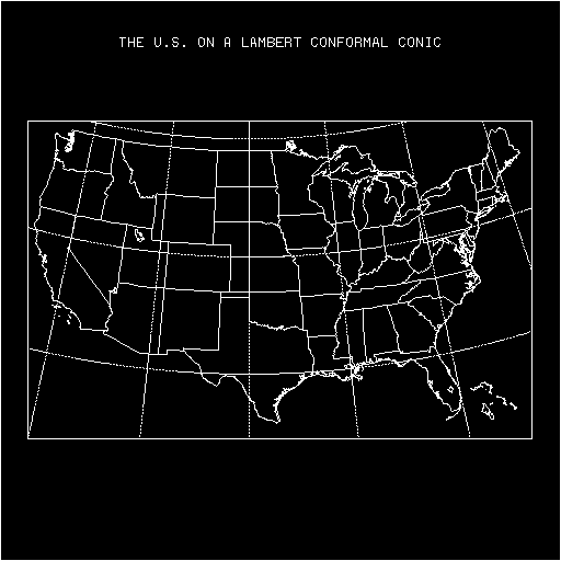
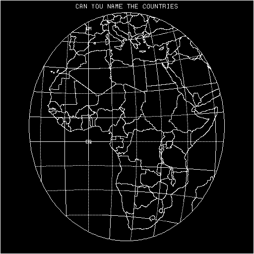
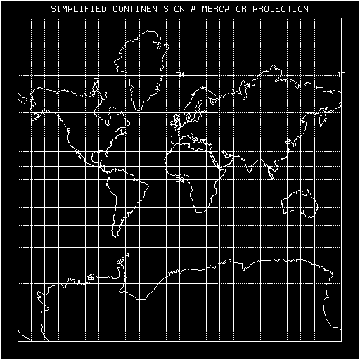
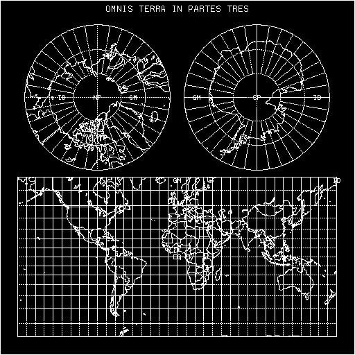
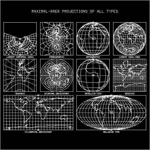
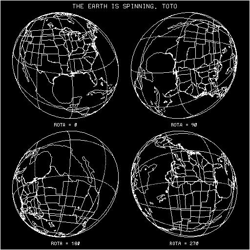
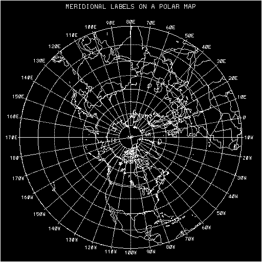
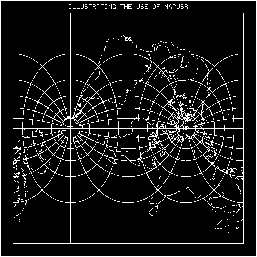
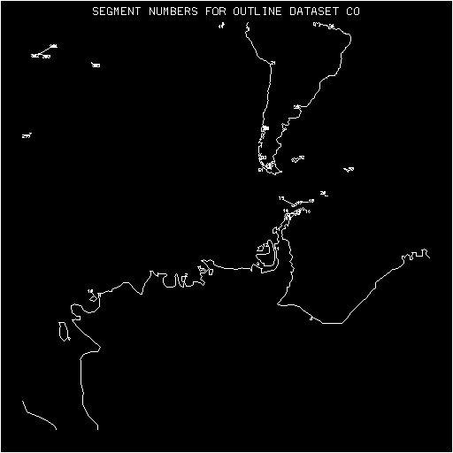 (frame 1)
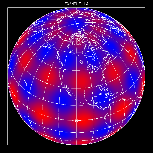
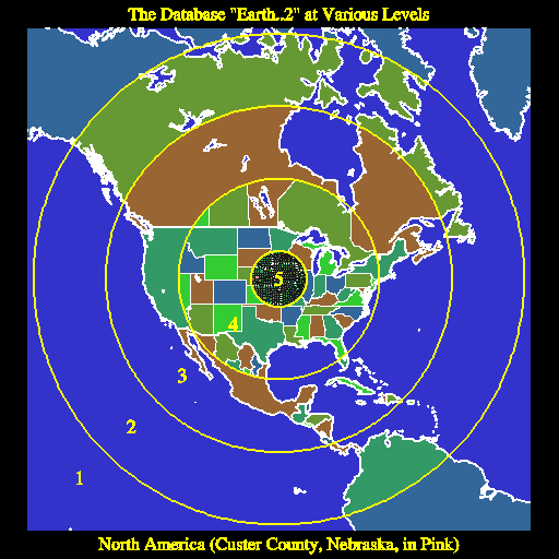 (frame 1)
Below is frame 4, which shows Tierra del Fuego at the very low resolution of the old database 'CO':
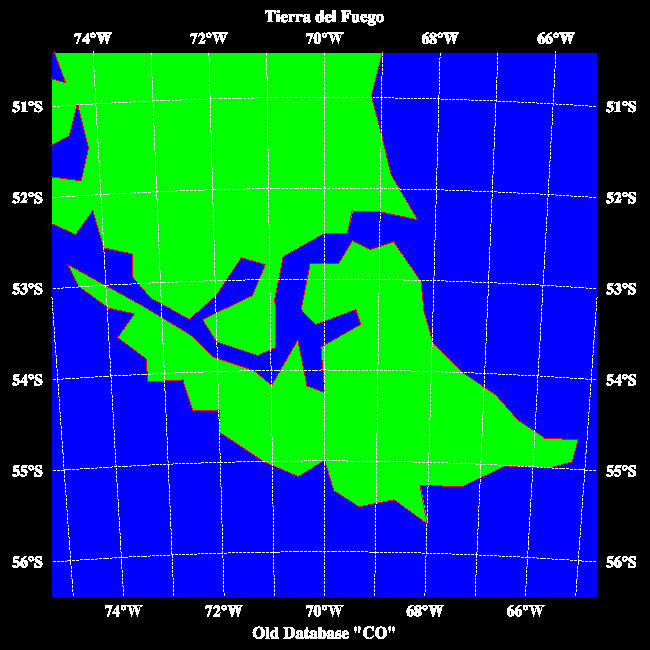 (frame 4)
Here is the same area at the higher resolution of "Earth..2":
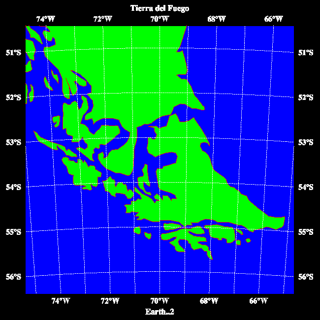 (frame 5)
And, finally, here is the same area at the highest resolution of the RANGS/GSHHS database:
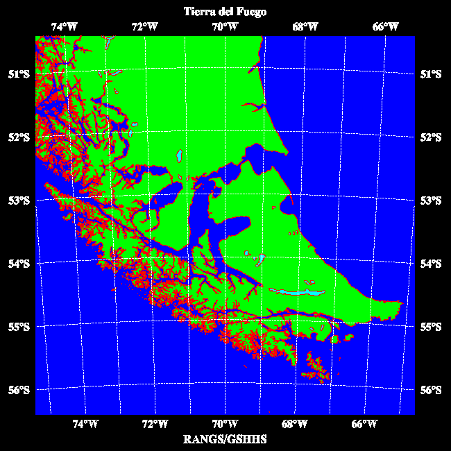 (frame 6)
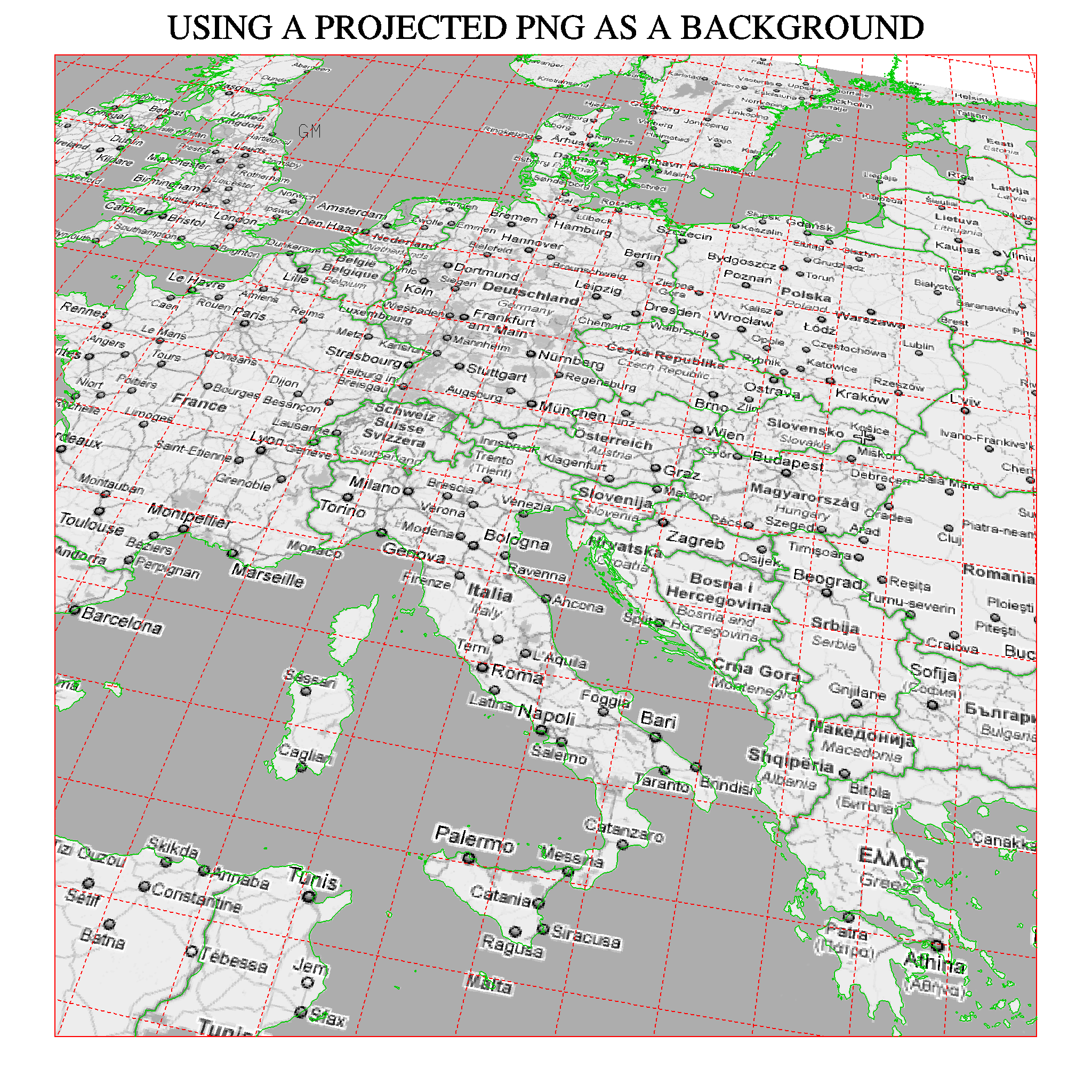
A two-degree lat/lon grid, in red, and geopolitical outlines from the database "Earth..4", in green, are drawn on top of the transformed PNG.
Of course, the PNG need not contain a map; for example, terrain data can be displayed to good effect.
It is hoped that, eventually, NCAR Graphics will be capable of displaying true color, making this feature even more useful.

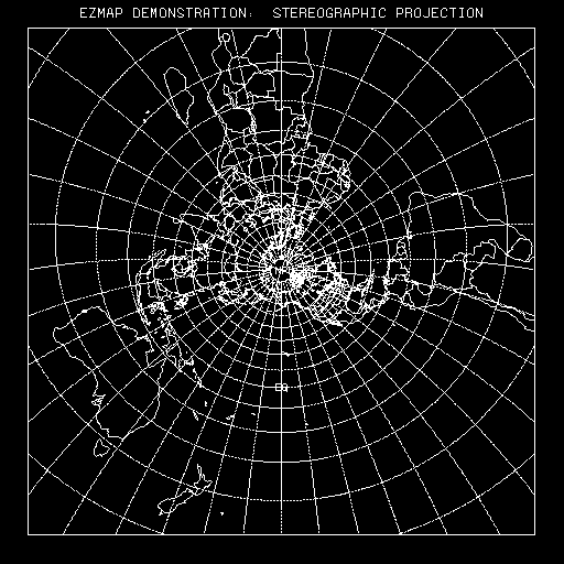 (frame 1)
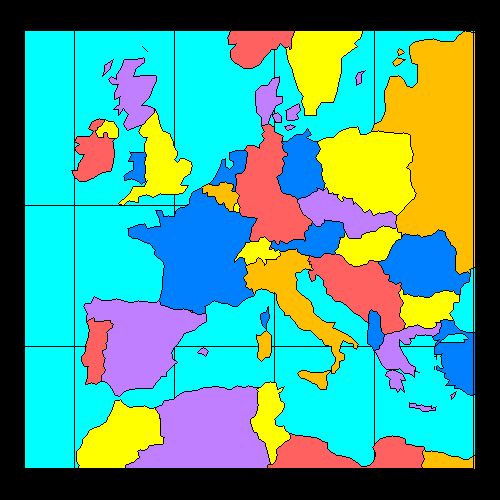
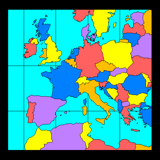
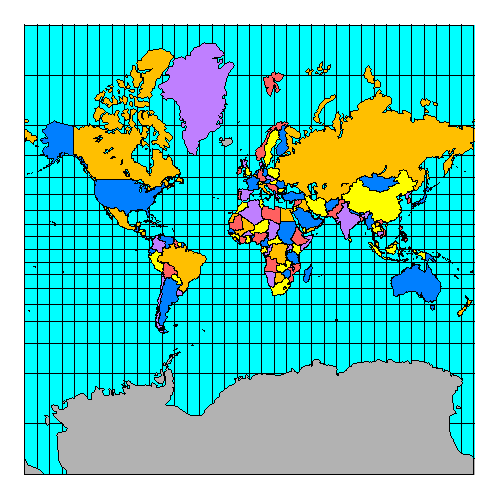
The following CONPACK example illustrates the use of the satellite-view projection and various routines from the package EZMAPA:
Cicely Ridley, Jay Chalmers, and Dave Kennison (the current curator) have all had a hand in the creation of EZMAP.
Lee, Tso-Hwa, "Students' Summary Reports, Work-Study Program in Scientific Computing". NCAR, 1968.
Parker, R.L., "2UCSD SUPERMAP: World Plotting Package".
Steers, J.A., "An Introduction to the Study of Map Projections". University of London Press, 1962.
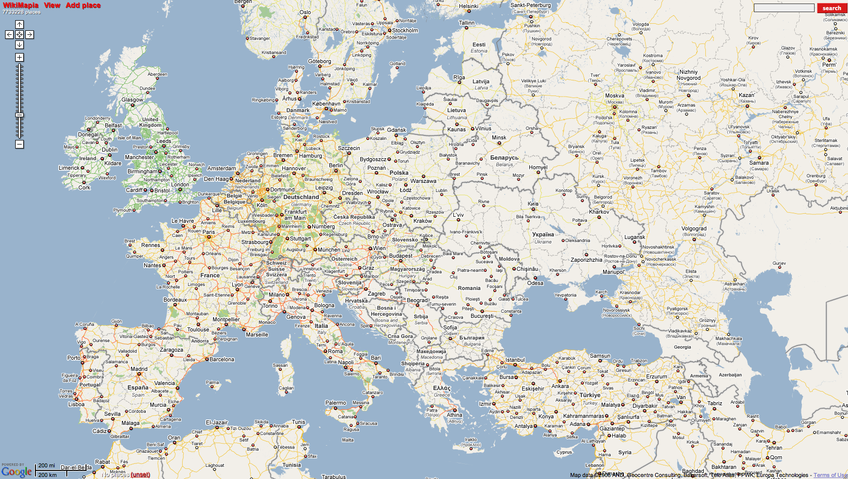