PDF Output


What is PDF?

Overview

PDF (Portable Document Format) is a device independent page description format introduced by Adobe Systems Incorporated in the early 1990s. The goal of PDF is to enable users to exchange and easily view electrionc documents independent from the environment in which they were created. PDF uses the same imaging model for graphics and text as Adobe PostScript, but PDF defines a more structured format to allow for improved navigation and efficiency. PDF is a static format, rather than a general-purpose programming language like PostScript. PDF source is written in ASCII, but several encodings are provided to encapsulate binary data.

PDF fully integrates text and graphics. In fact, text characters are viewed as graphic objects in PDF, just as they are in PostScript.

PDF is the native file format of the Adobe Acrobat Family of products. The Adobe Acrobat reader is the most common PDF viewer. It is available for free from the Adobe web site.

There are many PDF related books on the market. For a complete description of the format, see PDF Reference, Third Edition, version 1.4, published in 2001 by Adobe Systems Incorporated. However, if you are just viewing or automatically creating PDF, then there is no need for you to understand the actual language format.

Fonts

As a minimum a PDF interpreter supports at least the thirteen PostScript fonts: the Times family (regular, bold, italic, and bold-italic); the Courier family (regular, bold, oblique, and bold-oblique); the Helvetica family (regular, bold, oblique, and bold-oblique); and a symbol font containing lots of math symbols among others. Some interpreters support dozens or even hundreds of fonts.

References

Probably the only reference you will ever need for PDF is: PDF Reference Version 1.4 (3th edition).

Producing PDF Output from NCAR GKS

GKS Workstation Types for PDF output

PDF can be produced from the NCAR GKS package in either portrait mode (pictures displayed along the width of the paper or viewing window) or landscape mode (pictures displayed along the length). These two options are implemented in NCAR GKS as different workstation types. For an overview of workstation types in NCAR GKS, see the Workstation Functions documentation module.

The following table summarizes the PDF workstation types in NCAR GKS:

Table 4: NCAR GKS Workstation Types for PDF Output 
-------------------------
Workstation             
   type      orientation 
-------------------------
    11       portrait   
    12       landscape
-------------------------------------------------------

Output file names

The default file names of PDF output from NCAR GKS are of the form gmetaXX.pdf, where "XX" is the workstation ID used in the GOPWK call.

As an example, let's look at a simple Fortran code fragment that opens and activates a workstation that produces a PDF file in landscape mode:

      CALL GOPKS(3,IDUMMY)
      CALL GOPWK(3,0,12)
      CALL GACWK(3)
After this code is executed, a file named "gmeta3.pdf" will be produced that contains the desired PDF output. It is possible to override the default file name. This is done in the same way as overriding the output name for PostScript output. .

Simultaneously Active PDF Workstations

Only a single PDF workstation can be open at a time. If you try to open a pdf workstation while another one is open, a warning message will be issued.

Accessing fonts

You can access the thirteen PostScript fonts directly for output to PDF files generated by NCAR GKS (rather than accessing the stroked or filled characters of the NCAR Graphics package). This is done automatically using the GKS function GTX. A translation has been effected for most of the fontcap-defined fonts and filled fonts available via the Plotchar package. By selecting fonts with the GKS function GSTXFP and using GTX, you will get PostScript fonts in the resulting output file. These will not be stroked or filled representations of the characters, but characters to be rendered by the PDF interpreter in use.

There are equivalent PostScript characters for all of the characters from the filled fonts in Plotchar, except for a couple of the math symbols, and except for all of the WMO weather symbols. Additionally, the italic and bold italic fonts, not available in Plotchar, are available for the Helvetica, Times, and Courier font families.

There are no equivalents for all characters in all fontcap-defined fonts. For example, the script fonts and the old English font are entirely missing. Also things like the Zodiacal symbols from the NCAR Symbol Font are not available. If a requested character is not available from a PostScript font, NCAR GKS issues a warning message and suggests using Plotchar.

There are two big advantages to using PostScript fonts in place of Plotchar fonts. One is that there is a dramatic difference in PDF file sizes. Plotchar inserts either strokes or filled areas into the output stream in order to render its characters. There may be dozens of coordinates (with each coordinate pair requiring a dozen bytes in the output PDF) issued for a single character produced by Plotchar. Using the PostScript fonts requires using only a few bytes additional to those in the string to be rendered.

The second advantage to using PostScript fonts is that they will be rendered accurately at small sizes on low resolution output devices. A great deal of effort has gone into most PDF interpreters to accurately render characters at all sizes. When the characters produced by Plotchar get too small, some of the areas may fall between pixels on the output device and do not get plotted.

The following table summarizes the relationships between the PostScript fonts and the NCAR GKS fonts:

Table 5: Mapping between NCAR GKS fonts and PostScript fonts 
------------------------------------------------------------------------
NCAR GKS     NCAR GKS font name          PostScript equivalent
font number                                                               
------------------------------------------------------------------------
    1        default                     Helvetica                        
   -2        Hershey Cartographic Roman  Helvetica (scaled small)         
   -3        Hershey Cartographic Greek  Greek from Symbol font (scaled)  
   -4        Hershey Simplex Roman       Helvetica                        
   -5        Hershey Simplex Greek       Greek from Symbol font           
   -6        Hershey Simplex Script      none                             
   -7        Hershey Complex Roman       Times-Roman                      
   -8        Hershey Complex Greek       Greek from Symbol font           
   -9        Hershey Complex Script      none                             
  -10        Hershey Complex Italic      Times-Italic                     
  -11        Hershey Complex Cyrillic    none                             
  -12        Hershey Duplex Roman        Helvetica                        
  -13        Hershey Triplex Roman       Times-Bold                       
  -14        Hershey Triplex Italic      Times Bold-Italic                
  -15        Hershey Gothic German       none                             
  -16        Hershey Gothic English      none                             
  -17        Hershey Gothic Italian      none                             
  -18        Hershey Math Symbols        math symbols from Symbol font    
  -19        Hershey Symbol Set1         none                             
  -20        Hershey Symbol Set2         none                             
  -21        NCAR Helvetica              Helvetica                        
  -22        NCAR Helvetica-Bold         Helvetica-Bold                   
  -23        none                        Helvetica-Oblique                
  -24        none                        Helvetica-BoldOblique            
  -25        NCAR Times-Roman            Times-Roman                      
  -26        NCAR Times-Bold             Times-Bold                       
  -27        none                        Times-Italic                     
  -28        none                        Times-BoldItalic                 
  -29        NCAR Courier                Courier                          
  -30        NCAR Courier-Bold           Courier-Bold                     
  -31        none                        Courier-Oblique                  
  -32        none                        Courier-BoldOblique              
  -33        NCAR Greek                  Greek from Symbol font           
  -34        NCAR Math Symbols           math symbols from Symbol font    
  -35        NCAR Text Symbols           text symbols from Symbol font    
  -36        NCAR Weather 1              none                             
  -37        NCAR Weather 2              none                             
------------------------------------------------------------------------

GKS ESCAPE functions controlling PDF Output

In what follows, details are given on the escape functions in NCAR GKS that apply specifically to PDF (and PostScript) workstations. These escape functions control aspects of the PDF output that are PDF-specific and lie outside the scope of the GKS Standard. The user interface to these escape functions is via the entries NGSETI, NGSETR, and NGSETC.

Positioning PDF output on the page

The GKS Standard requires that the aspect ratio of a plot be preserved in its mappings from world coordinates to normalized device coordinates ( NDC ) to device coordinates. In particular this means that in mapping the default NDC unit square onto the display surface of an output device it should be mapped onto a square. This prevents things like circles being turned into ellipses and squares being turned into rectangles. In the default case, PDF output is placed on the output page in a square that is centered on the page.

On certain occasions it may be desirable to use the entire area of a rectangular output page, or even to change the aspect ratio of the plot. PDF output from NCAR GKS can be made to occupy any position on the page by way of setting coordinate boundaries using control parameters LX, LY, UX, UY. These numbers are integers and specify corner points (LX,LY) and (UX,UY) that bound the output on the page. The numbers are specified in the default PDF coordinate space where one unit corresponds to 1/72 of an inch. In order to preserve aspect ratio, the output rectangle should be specified as a square. For example, if you want your output to occupy a square in the upper left part of a page in portrait mode, you would make calls such as:

      CALL NGSETI('LX',50)
      CALL NGSETI('LY',500)
      CALL NGSETI('UX',300)
      CALL NGSETI('UY',750)
Values must be specified for all four parameters LX, LY, UX, and UY.

Using the full page

A common desire is to use a full printed page to display pictures. As discussed earlier, unless you can live with the undesirable results of simply scaling your plot to fill the entire page, you will need to restrict the drawable part of your original plot to using an aspect ratio that is compatible with the output page (11/8.5). To produce output on a full page, you will probably want to chose the landscape mode PDF workstation. In the default case, a plot in landscape mode will be exactly what it was in portrait mode, except rotated clockwise by 90 degrees. Using the positioning parameters LX, LY, UX, and UY requires that you understand how landscape mode is implemented in the PDF workstations. PDF does not understand landscape and portrait modes - in the case of printing to and 8.5" x 11" page, the area bounded by the PDF coordinates (0,0) and (612,792) is printed on the page. The concept of landscape mode is implemented in PDF by rotating and translating a portrait mode plot. In landscape mode the parameters LX, LY, UX, and UY specify default PDF coordinates (one unit equals 1/72 of an inch) that define the corner points (LX,LY) and (UX,UY) of a rectangle. The NDC unit square will be mapped onto this rectangle, then this rectangle will be rotated by 90 degrees clockwise about the point (LX,LY) and then translated by an amount so that the lower left corner of the rotated plot will coincide with the original lower left corner (LX,LY). In specifying the values for LX, LY, UX, and UY realize that, if the final plot is to fill the page in landscape mode, the value specified for UX would run off the right of an 8.5" x 11" page if plotted in portrait mode.

For example, suppose that you choose a landscape mode PDF workstation and specify the following values:

     LX = 50
     LY = 50
     UX = 742
     UY = 562
Here is what happens using these specifications. The NDC unit square will first be mapped to fit in the rectangle with lower left corner (50,50) and upper right corner (742,562) [if drawn in portrait mode, this plot would run off the right of an 8.5" x 11" piece of paper]. This rectangle is then rotated by 90 degrees clockwise about the point (50,50), giving a rectangle with coordinates (50,50) at the upper left and (562,-642) at the lower right. This rectangle is then translated vertically by 692, giving a rectangle with corner points (50,50) at the lower left and (562,742) at the upper right. Since the extreme corners of a printed 8.5" x 11" page are (0,0) and (612,792), the above rectangle will fit entirely within the page. The above settings distort the aspect ratio of the plot by elongating it and then rotating it so that it fits on the page.

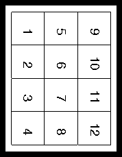
You will probably not want to distort the aspect ratio of your plots when plotting to a full page, since the plots will have characters that look funny, circles will appear as ellipses, and so forth. In this case you should start with a plot such that the drawable part has an aspect ratio suitable for filling an 8.5" x 11" page. Figure 19 and Figure 20 illustrate this. The landscape version in Figure 20 was positioned by using workstation type 12 (landscape mode) and making the following calls:

      CALL NGSETI('LX',50)
      CALL NGSETI('LY',50)
      CALL NGSETI('UX',742)
      CALL NGSETI('UY',742)
Notice that the aspect ratio of the drawable part of the original plot is 4 to 3, and white space is left above the plot in order for it to be plotted correctly after it is rotated and translated. See the above discussion on positioning your output in order to understand the above subroutine calls.
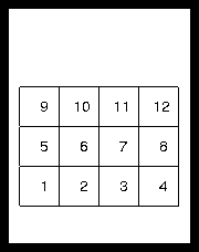
Figure 19 - Plot in portrait mode

Figure 20 - Plot from Figure 19 scaled to fill the page in landscape mode

Notes on page positioning parameters:

Some experimenting with various settings for the workstation types and values for LX, LY, UX, and UY should give you a feeling for how they work.

Overriding Default File Names

Names for the PDF output files can be assigned to override the default names. The name for the output file must be known at the time the workstation is opened with GOPWK. Making a call:
      CALL NGSETC('ME','pdf_file_name')
just prior to the GOPWK call that opens the workstation will assign the desired name to the output file. The name can be up to 256 characters long.

You can assign 'stdout' to the output file name with a call to NGSETC and the output will go to standard out. This is only practical when you are writing to a single PDF output file. Also, be aware that errors or warnings are usually written to the standard output file and intermingling these with the output PDF will corrupt the PDF.

Selecting a color model

By default, PDF produced from NCAR Graphics uses the RGB color model. You can make the PDF output use the CMYK color model (particularly useful in printing) by making a call
      CALL NGSETI('CM',IVAL)
where IVAL=0 (IVAL=1 selects the default RGB model).

The above call must be made just prior to the GOPWK call that opens the PDF workstation.

Background color.

Just as for output to NCGM or X11 windows, the value for GKS color index zero controls the background color setting for PDF output. By default, the background color is applied to the normalized device coordinate viewport. If you want to have the background color apply to the entire output page for a given PDF workstation, make the calls:
      CALL NGSETI('Workstation',WKID)
      CALL NGSETI('Full background',1)
where WKID is an integer workstation identifier. The setting for full background will apply only to the workstation specified in the most recent NGSETI call that sets the workstation ID.
Line style attributes

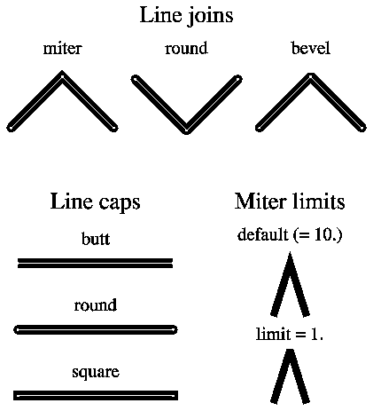
PDF has several line style attributes that are not part of GKS. Control over these attributes can be obtained using NGSETI calls. Figure 21 illustrates all of the line style attributes discussed in this section.

Line joins

The line join type controls the appearance of how line segments are connected. There are three possible values for the line join parameter: 0 for miter joins; 1 for rounded joins; 2 for bevel joins. For mitered joins, the edges of the line segments are extended until they meet. This join is also affected by the miter limit. For rounded joins, the line segments are joined with a circle at the join center where the circle has radius equal to the line width. For bevel joins, the line segments are drawn with butt ends (see the discussion of line caps) and the notch at the larger angle between the segments is filled with a triangle. Rounded joins are the default for PDF produced from NCAR Graphics. Values for line join can be set by making the appropriate NGSETI call. See Figure 21 for an example.

Line caps

The line cap attribute controls how the ends of line segments are stroked. There are three possible values for the line cap parameter: 0 for butt caps; 1 for round caps; 2 for projecting square caps. For butt caps, the line segments are terminated with square ends perpendicular to the line path. For round caps, the line segments are terminated with semicircles centered at the line endpoint and having a radius equal to the line thickness. Projecting square caps are the same as butt caps except the cap is extended beyond the line end points by half a line width. Round caps are the default for PDF produced from NCAR Graphics. Values for line cap can be set by making the appropriate NGSETI call. See Figure 21 for an example.

Miter limits

If, for mitered line joins, line segments meet at a very acute angle, then the mitered join can result in a spike that extends significantly beyond the intersection of the segments. To prevent this, PDF switches from a mitered join to a beveled join at an angle that is controlled by the miter limit parameter. The smaller the miter limit is, the less tolerant PDF is of exaggerated spikes at line joins. The default setting for the miter limit is 10. and the smallest the miter limit can ever be is 1. Setting the miter limit to 1. will essentially result in beveled line joins; setting the miter limit to values much higher than 10. will result in long spikes at lines joined at acute angles. Values for the miter limit can be set by making the appropriate NGSETI call.

Figure 21 - Line style attributes

Line widths

The GKS call GSLWSC can be used to set relative linewidths. The scale factor supplied to GSLWSC is applied to a default nominal line width. This nominal line width is implementation specific. You can control the size of this nominal linewidth for PDF output by using the "NO" (for "Nominal linewidth") parameter in a call to NGSETR. For example, the calls:
      CALL NGSETI('WO',WKID)
      CALL NGSETR('NO',2.)
would double the width of the nominal linewidth. This means that all lines would uniformly appear to be twice as thick as they would be in the default case. Figure 22 illustrates the result of changing the size of the nominal linewidth and then changing linewidths using GSLWSC. Just remember that the linewidth scale factors given to GSLWSC apply to the nominal linewidth, whereas setting a new value for the nominal linewidth will uniformly change the width of all lines.

Figure 22 - Line widths

Maximum number of points in a path

In drawing lines and filled areas, PDF builds a "path" and then strokes it out. The default limit on the maximum number of points in a path is 1300 in NCAR GKS. Polylines generated by NCAR GKS that exceed this limit are broken into paths that fall within the limit.

Filled areas present a more difficult situation than polylines in that the entire path must be presented in its entirety to be filled. For filled areas that exceed the limit on the maximum path size, software fill is utilized. This means the instead of presenting an entire path to the PDF fill operator, the area is filled by drawing a sequence of horizontal lines that are thick enough so that no gaps will be displayed. If you are generating filled areas that have more than 1300 points in them and you are using a PDF viewer that allows for more points than this, then you may want to consider increasing the limit on the maximum number of points in a path. You can do this by using the "PA" (or "Path size") parameter in an NGSETI call.

The savings in file size and interpretation time can be substantial (up to 50% or greater for files containing only large filled areas), but on the average (files that have one or two large filled areas) the savings are considerably more modest (1-10%). Setting the maximum path size to a small number can be used to force software fill, if that is ever desired.

Specifying spacing between software fill lines

When a filled area is requested that has more than the maximum number of points in it than are allowed (1300 in PDF output from NCAR GKS), software fill is implemented. This amounts to drawing a sequence of horizontal lines that will fill the given area. These lines are chosen to have a thickness so that no gaps result between fill lines. The distance between fill lines is specified as a real number in the range 0. to 1. (normalized device coordinate space). By default this value is .0005 which will result in 2000 lines being used to fill the largest possible area.

If you are plotting on a device with crude resolution and could get by with many fewer lines than the default, then you may want to consider resetting this value, which can be done by using the "FI" (or "Fill lines") parameter in an NGSETR call. If you are going to a super high resolution device, then it is possible that you will see discrete line ends on edges of filled areas that are at an acute angle. If this is undesired, then you may consider decreasing the value for FI (increasing the number of fill lines). Remember that by tuning the number of fill lines for a specific device may cause undesirable results on another device. Also, remember that software fill is not invoked unless the number of points in a filled area exceeds the maximum number of points allowed in a path.
Specifying spacing between hatch pattern lines

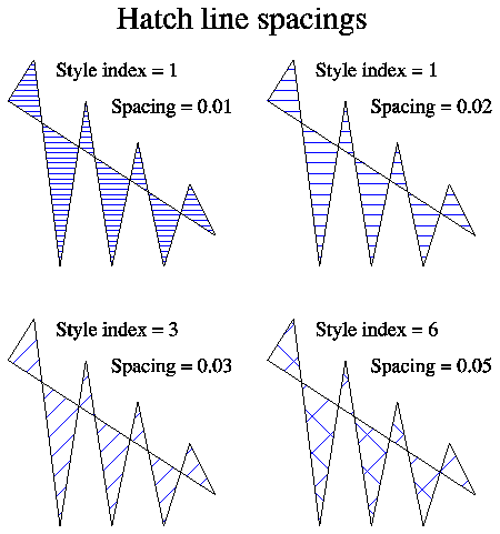
The spacing between lines composing a hatch fill pattern can be controlled with the NGSETR parameter "HA" (or 'Hatch spacing'). This applies only when the fill area interior style is set to 3 (see GSFAIS). The fill spacing is specified as a real number between 0. and 1. , inclusive (normalized device coordinate space).

Figure 23 - Hatch line spacings

Specifying the user coordinate space resolution

The default user coordinate space in PDF locates the origin at the lower left corner of the output page; the positive X axis extends horizontally to the right and the positive Y axis extends vertically upward. The length of a unit along either axis is 1/72 of an inch. Coordinates can be specified as either integers or real numbers.

In the default user integer coordinate space, an 8.5" x 11" output page in portrait mode would have X coordinates in the range 0 to 612 and Y coordinates in the range 0 to 792.

This is a fairly crude resolution, and when it is mapped onto a device space with much higher resolution (such as a 300dpi printer), the increased resolution of the output device is not fully utilized. PDF allows for scaling the user space so that you can use higher resolutions. The default user coordinate space in PDF produced from NCAR GKS scales the normal default user space by 25. For an 8.5" x 11" page in portrait mode this produces coordinates in the range 0 to 15300 in X and 0 to 19800 in Y. This space is the default user space scaled by 25. This scale factor can be controlled by the NGSETI parameter 'CO' (or 'Coordinate scale'). By default it is 25 as discussed above. If you are plotting to a device with crude resolution, then you might consider setting this scale factor to something smaller than 25. By doing so, the file sizes will be reduced in accordance with the smaller number of characters needed to represent the coordinates in the resultant PDF file. If you are plotting to a very high resolution printer and notice that you are not taking full advantage of the resolution of the device, then you may want to consider increasing the resolution of the PDF user space by setting the scale factor controlled by 'CO' to something larger than 25.


Links: GKS Index, GKS Home